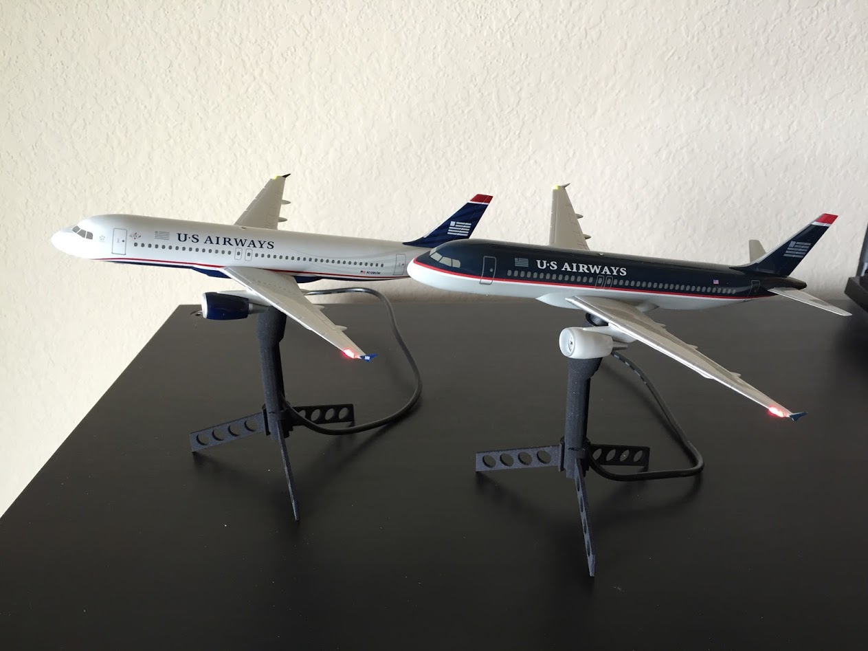
Lighted A320 Models
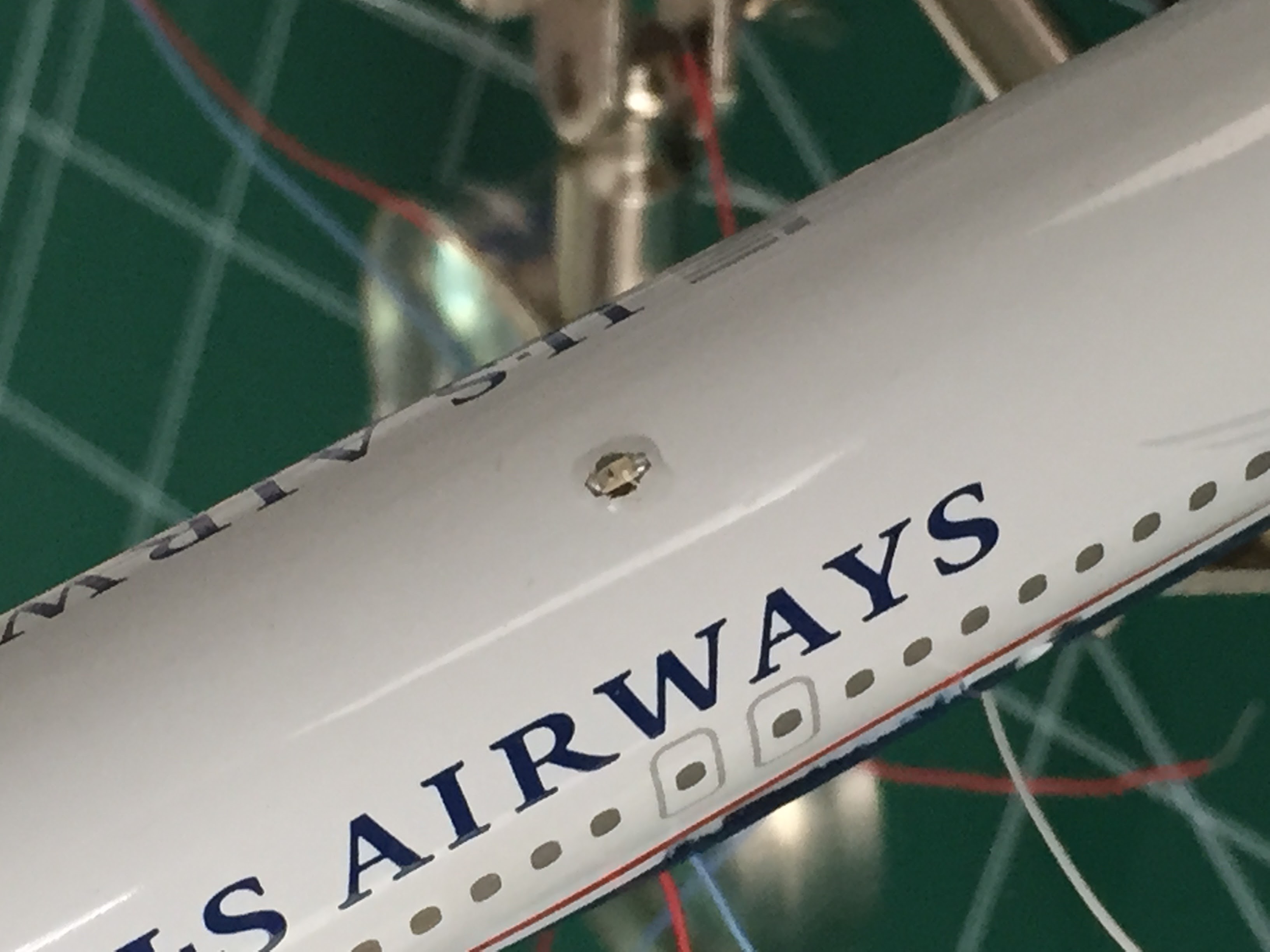
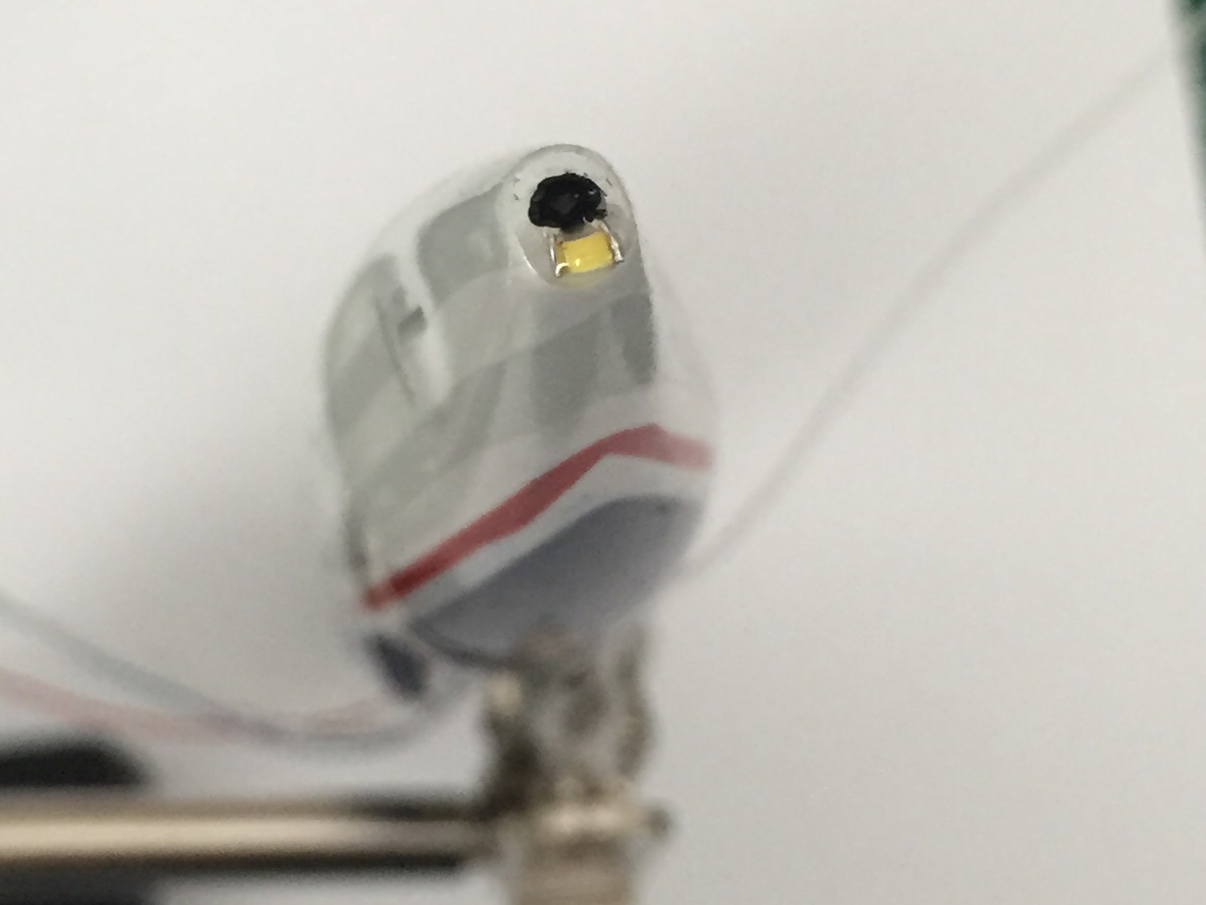
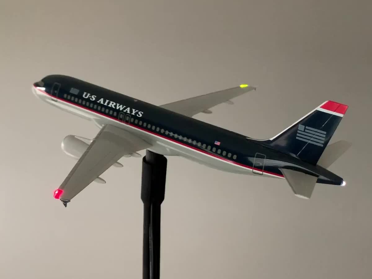 This is the navigation light strobe sequence based on the actual Airbus A320 aircraft. Airbus uses a set pattern while most Boeing aircraft appear to have independent timing for the top, bottom, tail and wingtip strobes.
Electronics v1
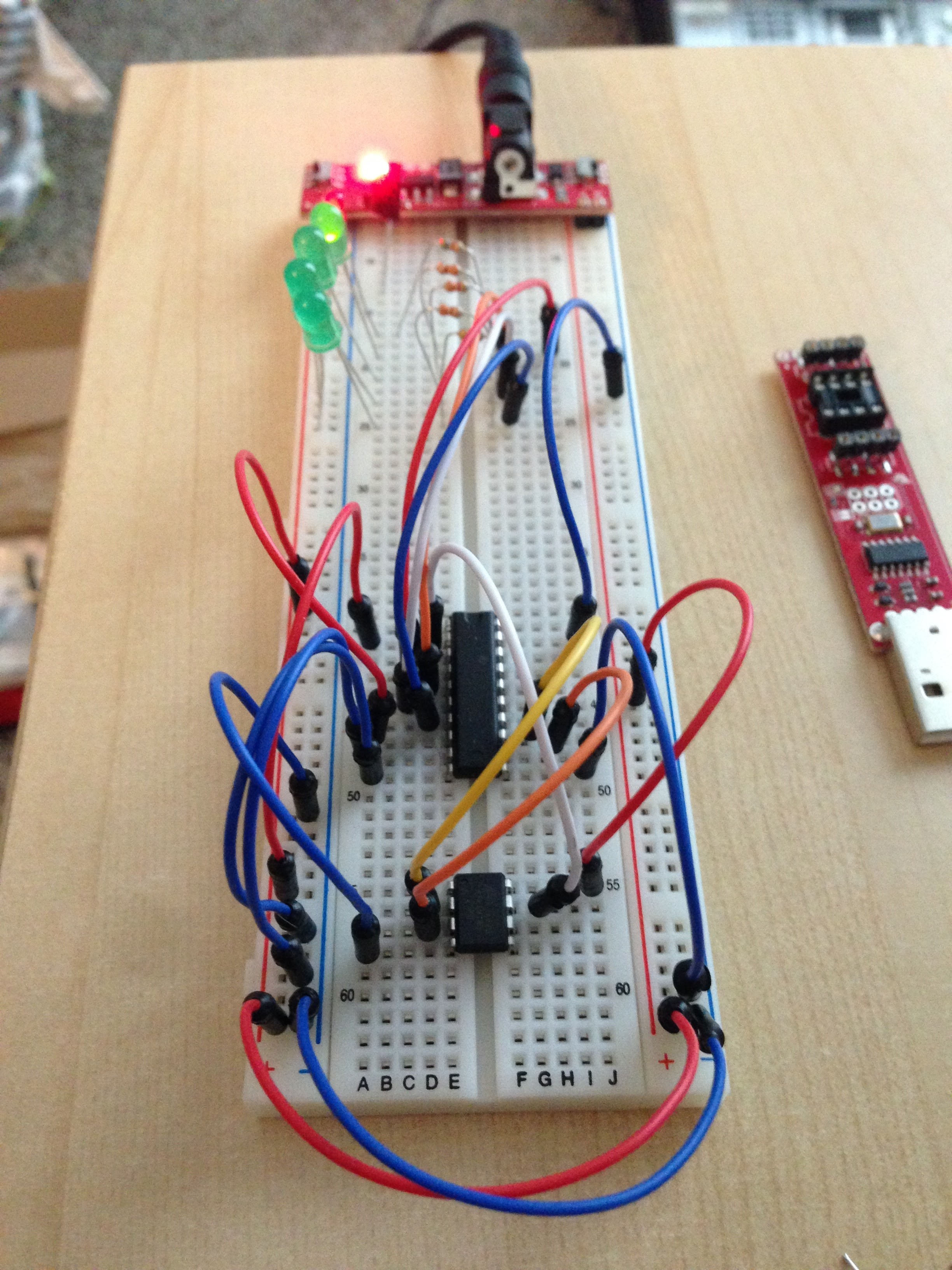
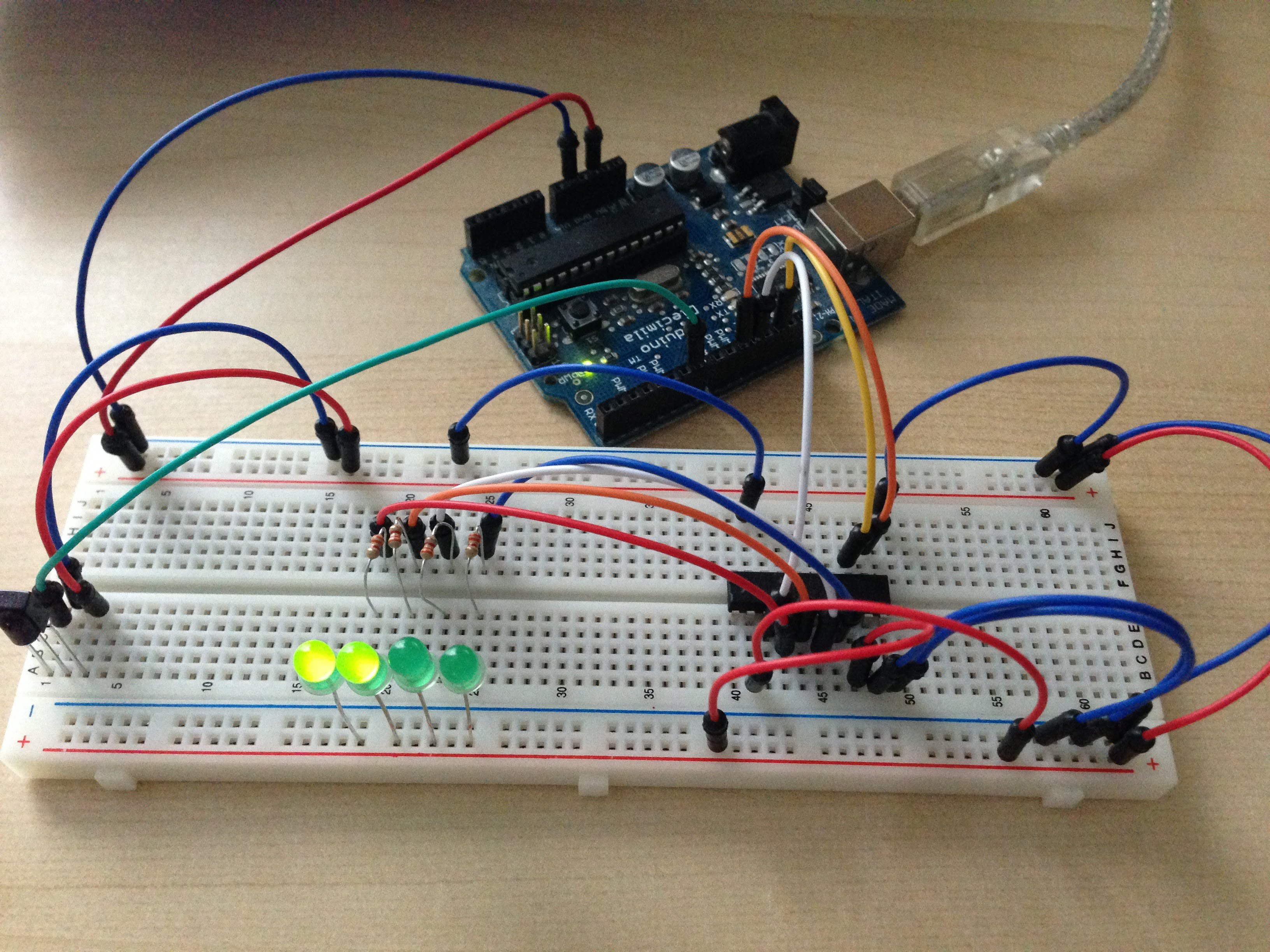 My first breadboard prototype of the idea using an Arduino Diecimila and TPIC6B595N shift register to control the LEDs. At this point I was just working out the blink timing and testing the IR remote control code.
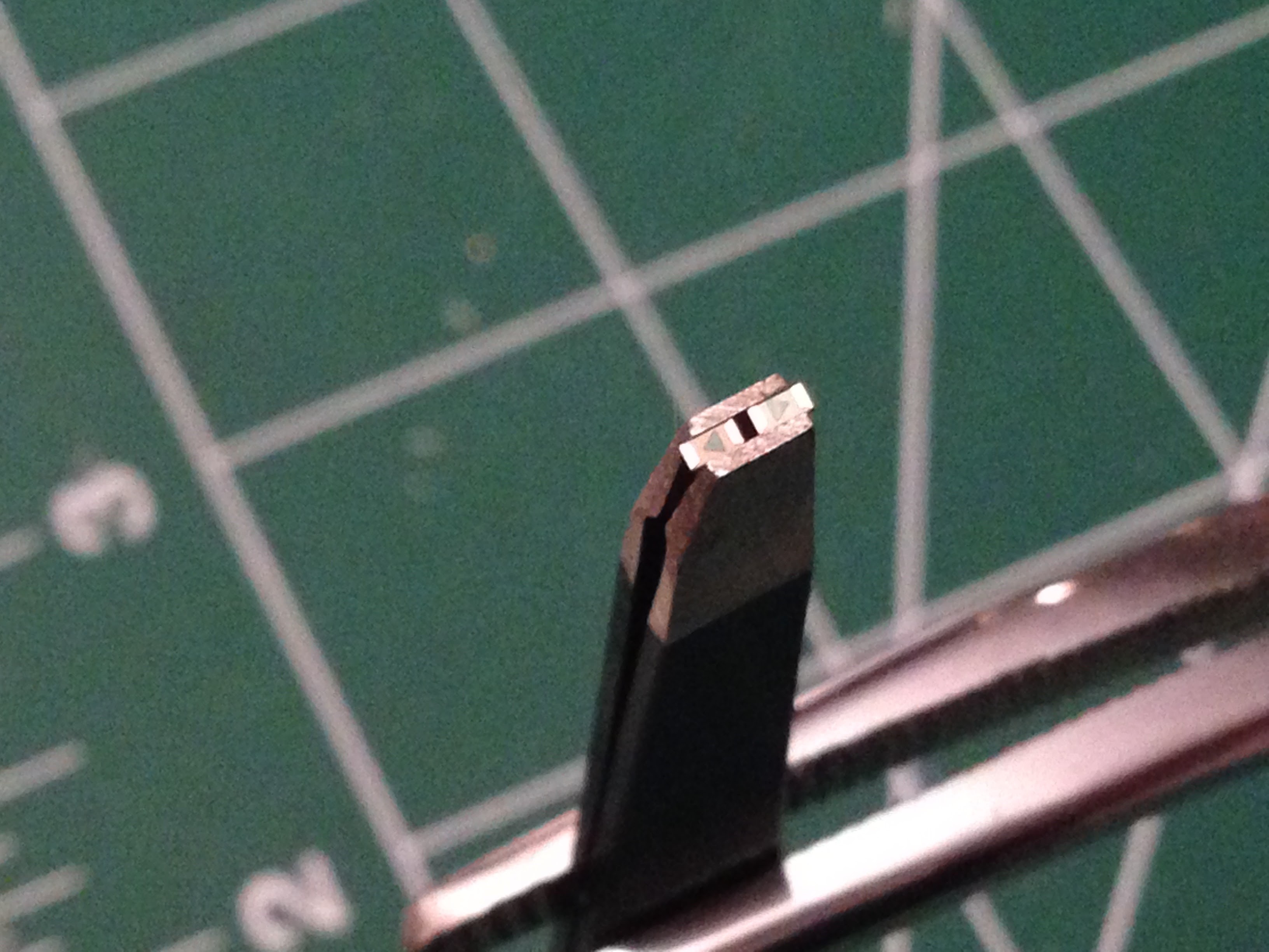
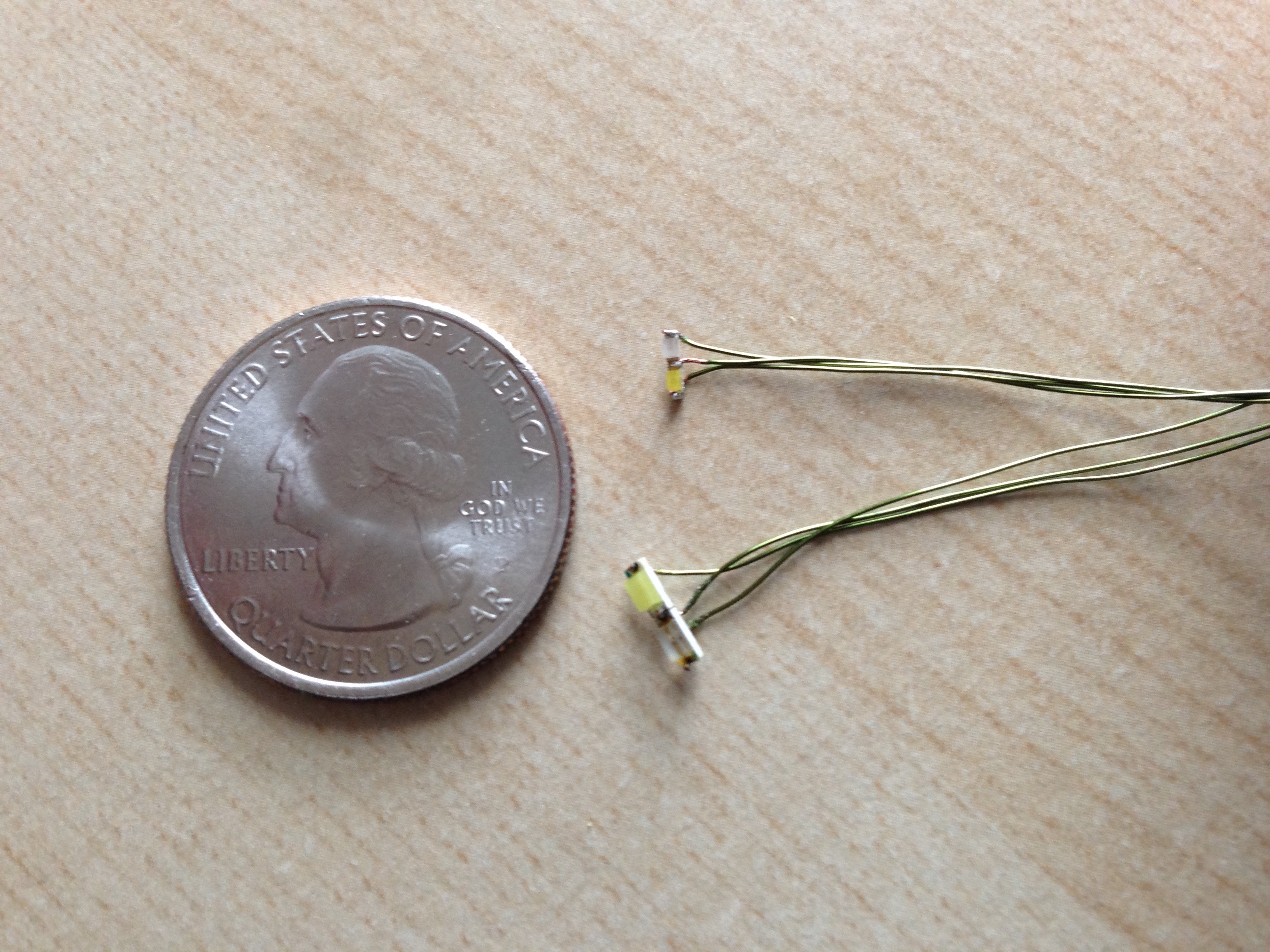 Comparing 1206 and 0603 surface mount LED size options for the wingtip lights. Of course the smaller ones look better and are much harder to solder.
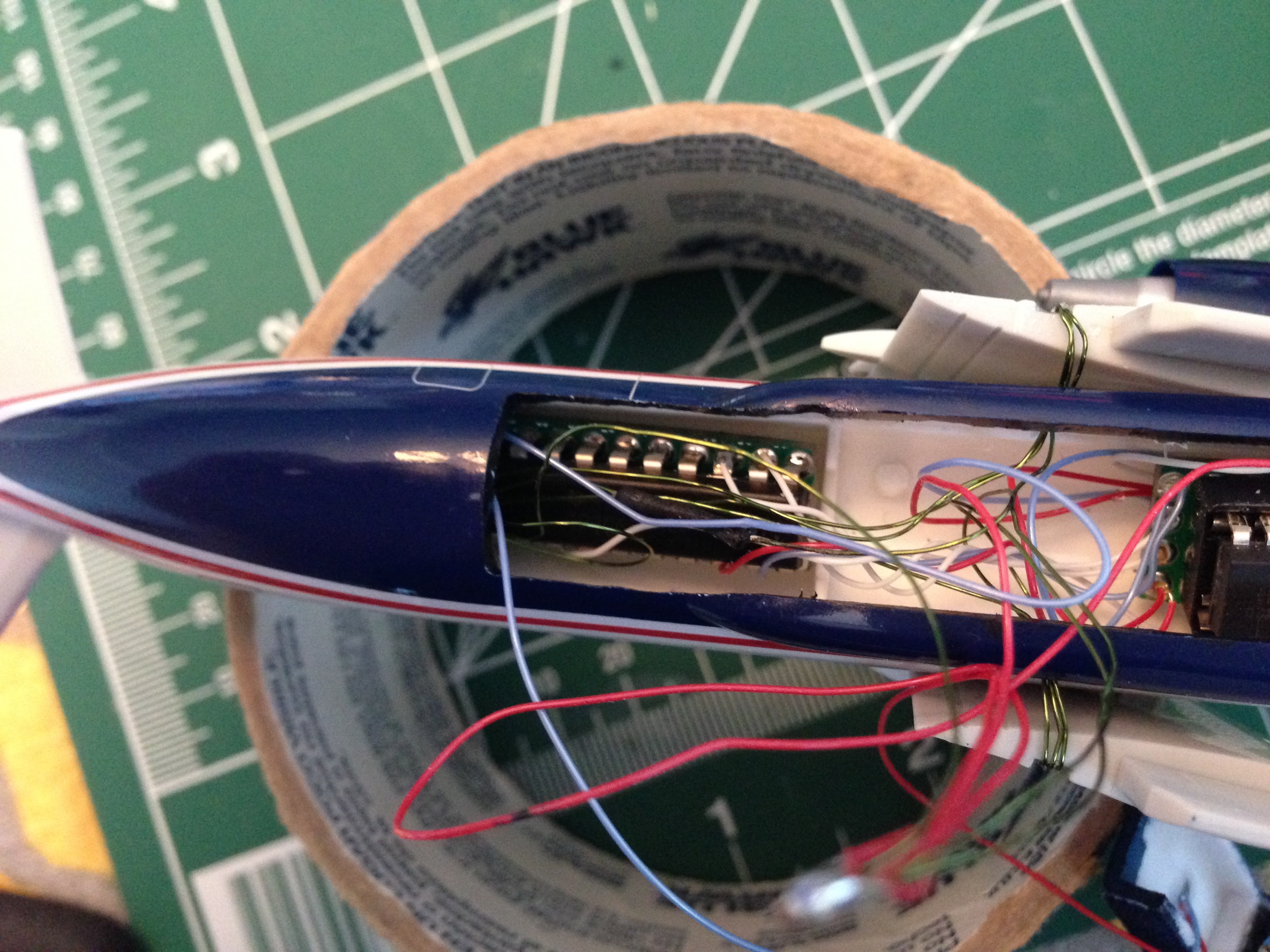
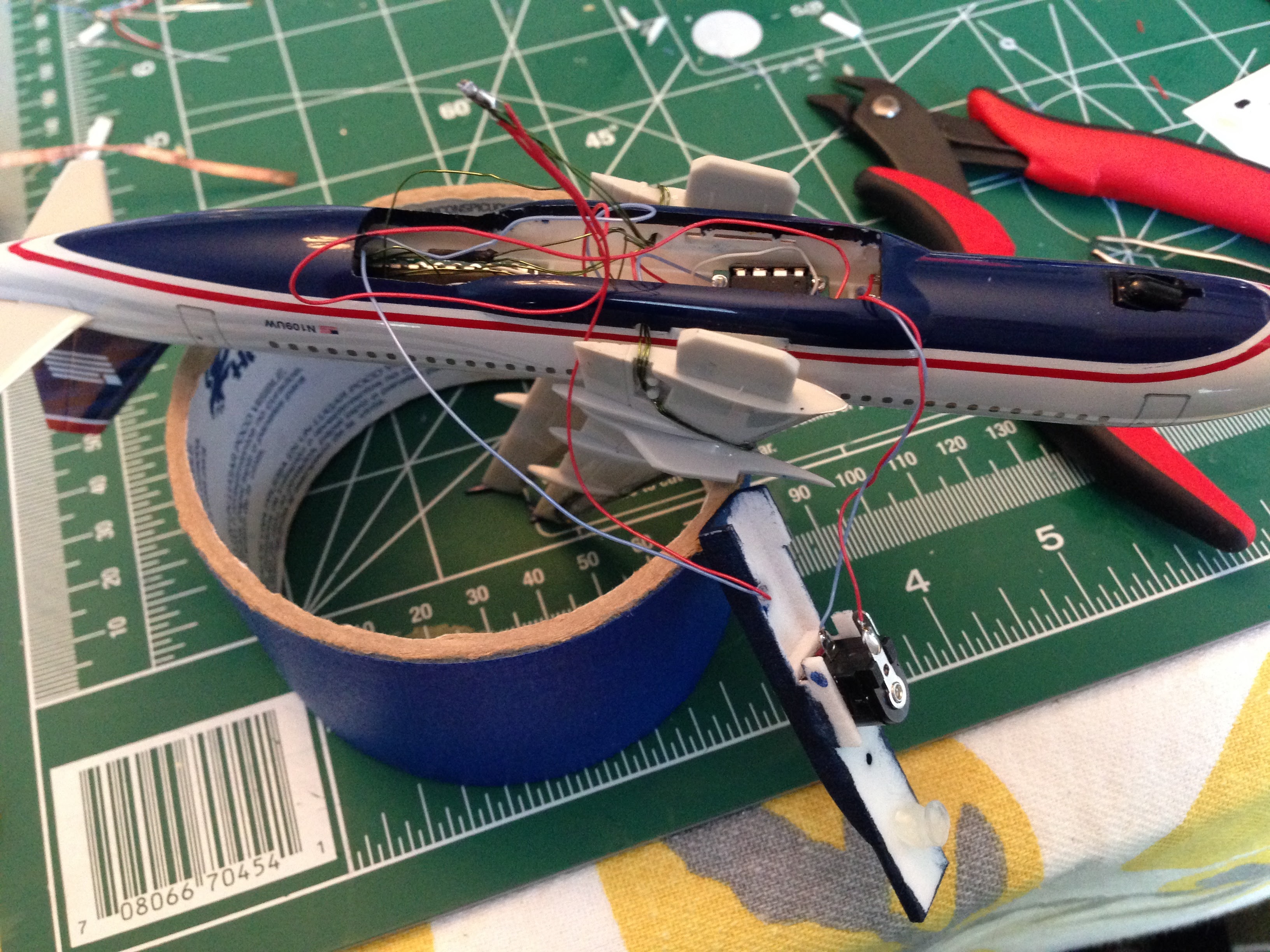
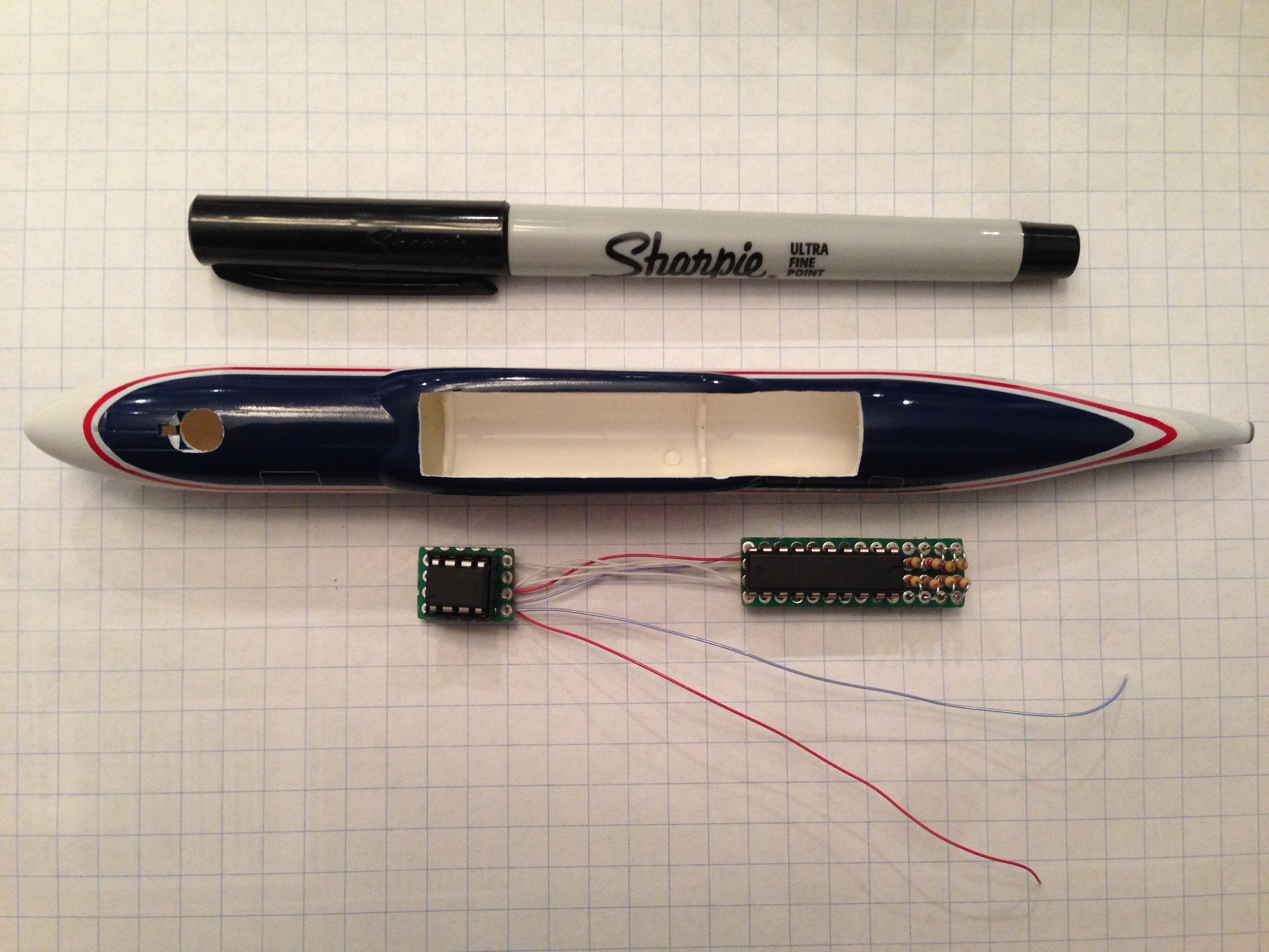 There is not a lot of space to work with inside of the fuselage. I had to split the ATTiny and shift register as a circuit board containing both wouldn't fit with the wing tabs inserted.
Electronics v2
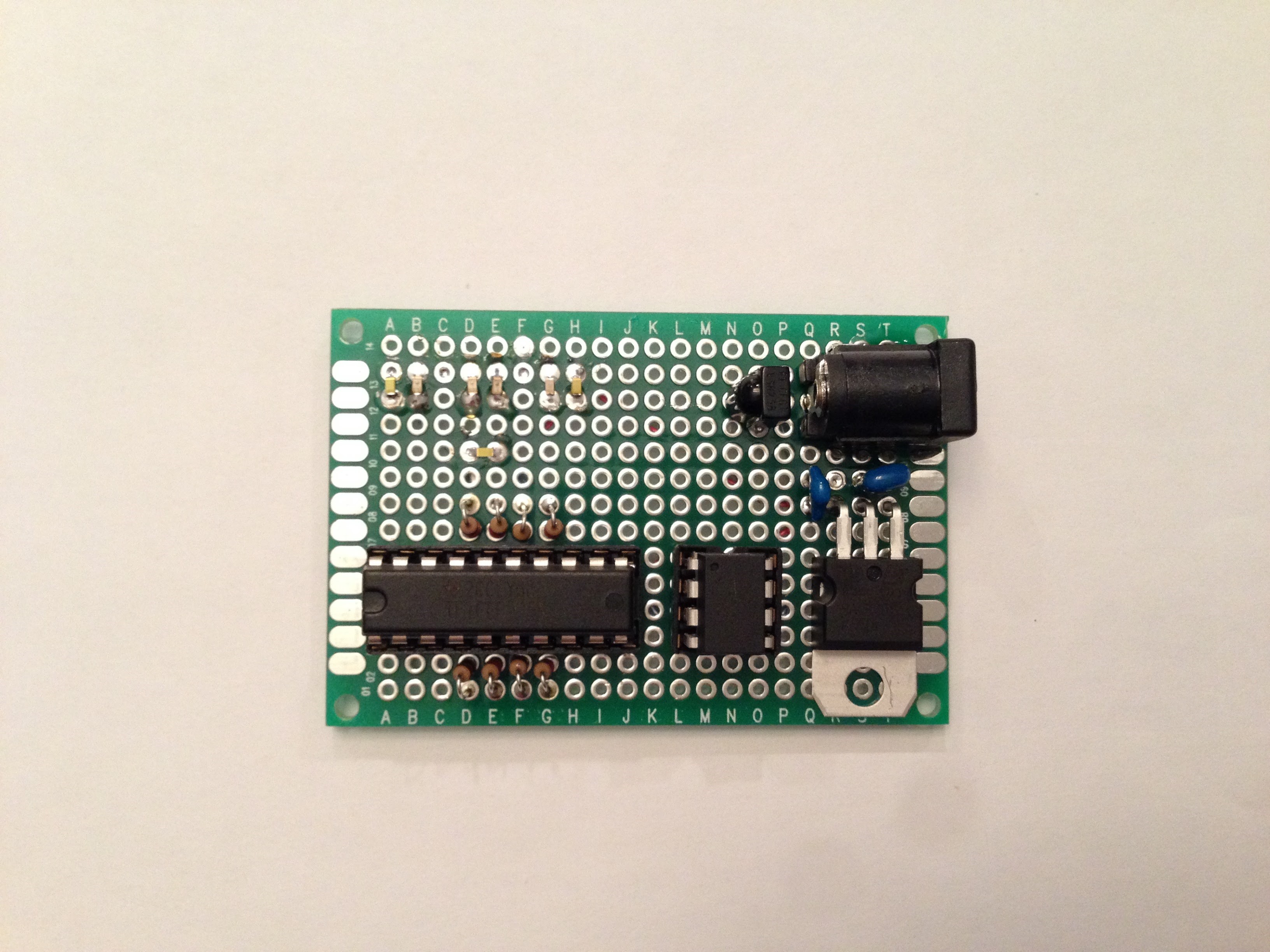
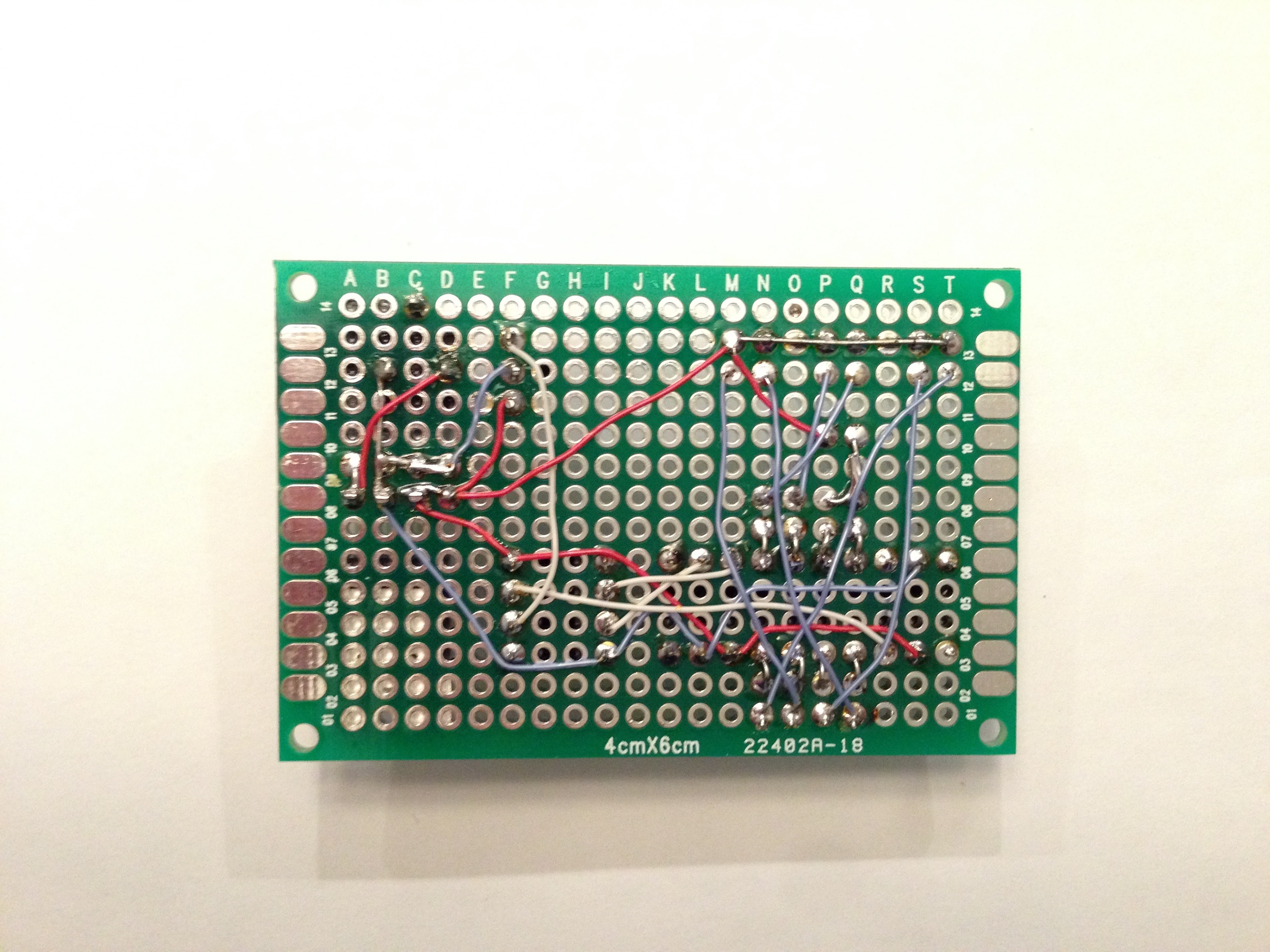
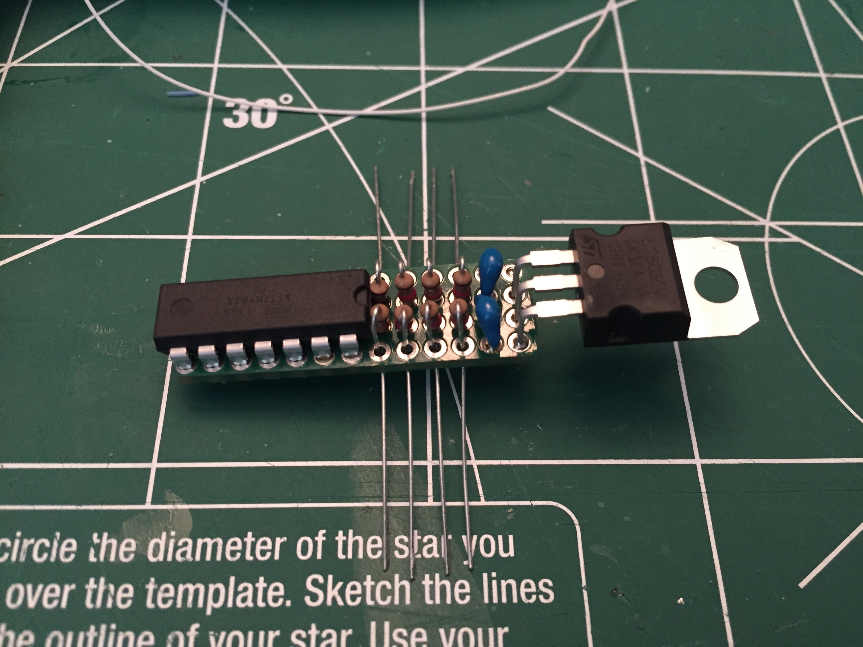
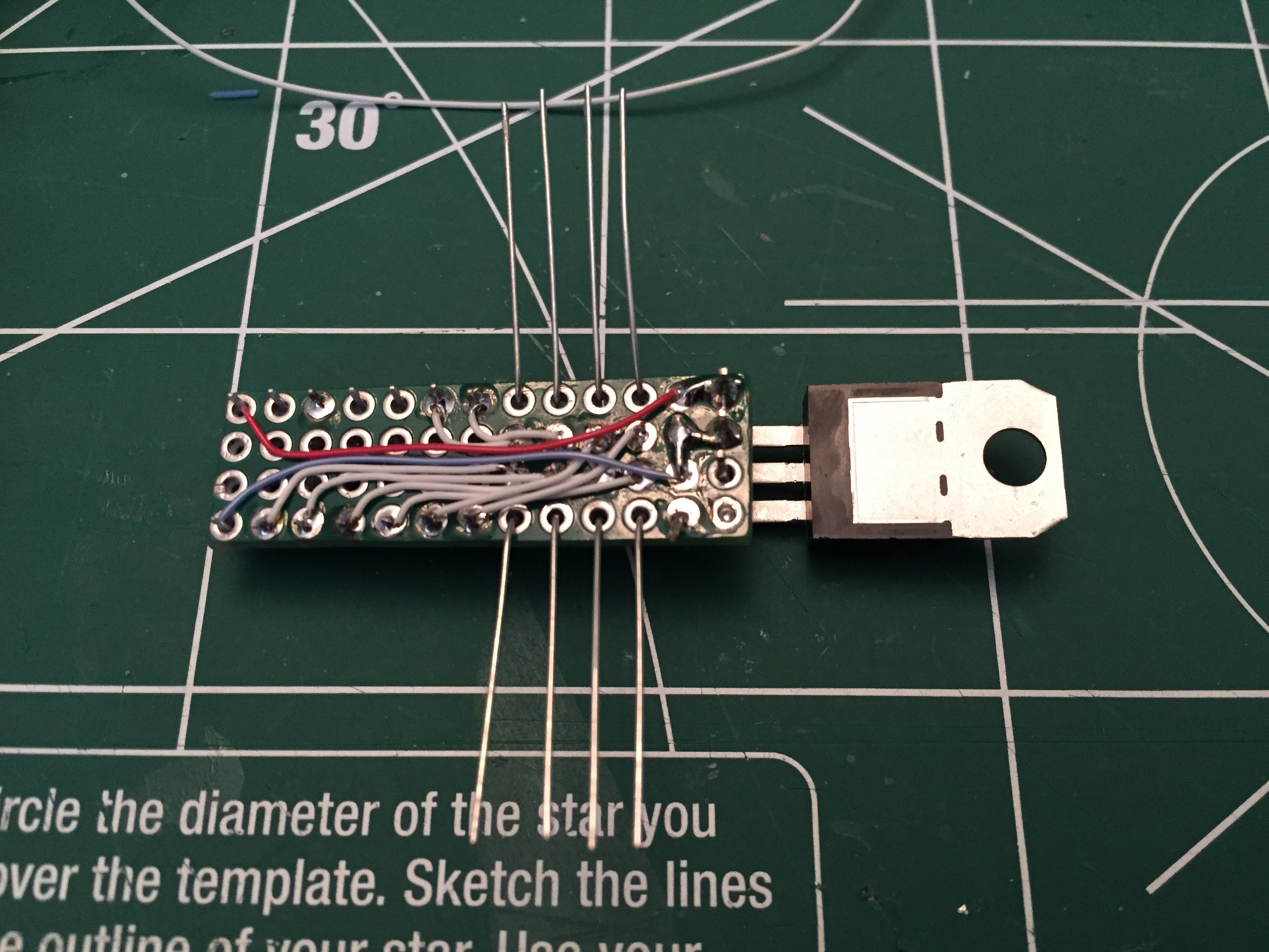
While the first version of the electronics assembly worked perfectly, it was bulky and I knew that I could design a more refined setup. I switched from the combination of ATTiny85 and shift register to the ATTiny84 which had enough pins so that I could run all of the LEDs and the IR receiver from a single chip. This let me combine all of the electronics into a single circuit board that would fit inside the tail section of the aircraft.
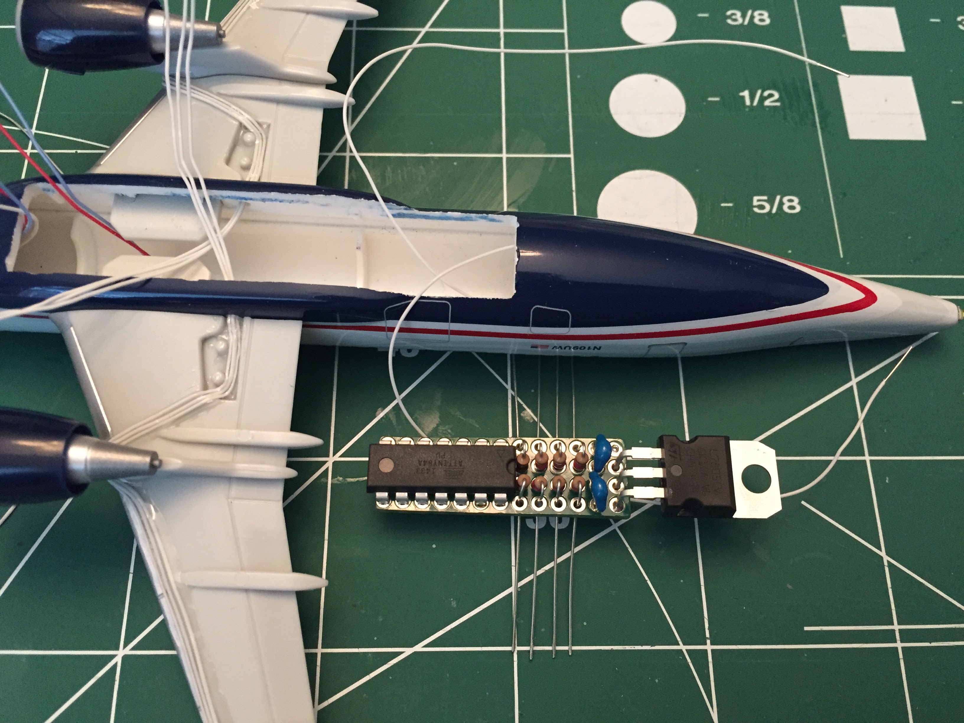 The entire electronics assembly (except for the IR receiver) is now small enough to fit into the tail section.
Electronics v3
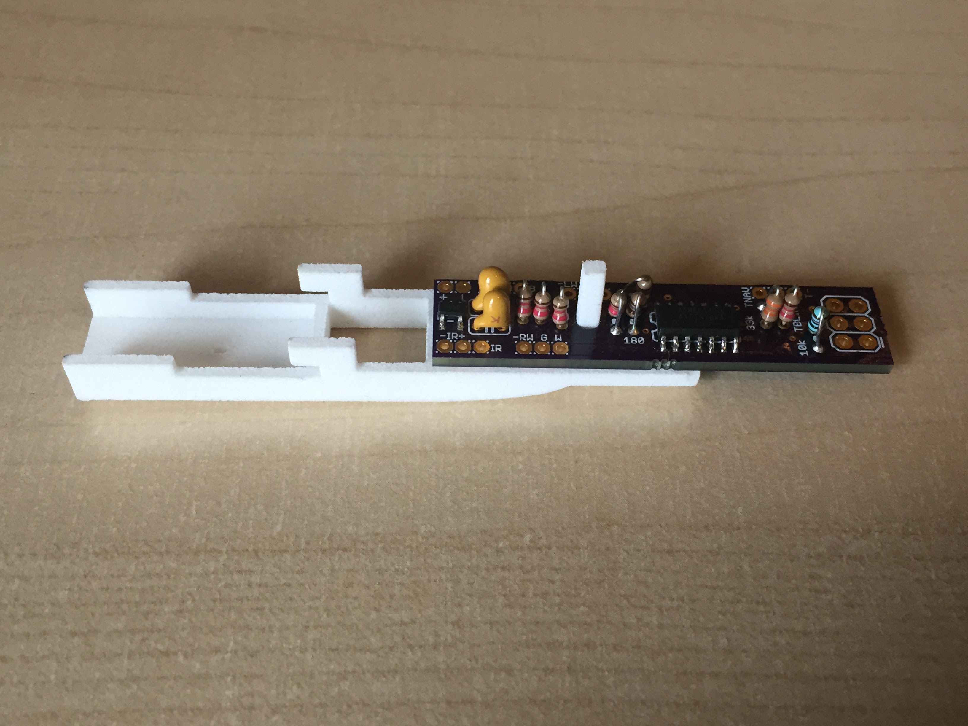
The final revision of my electronics package was functionally the same but involved designing a custom printed circuit board (PCB). I was able to switch to a surface mount version of the ATTiny84 and power supply which saved some space.
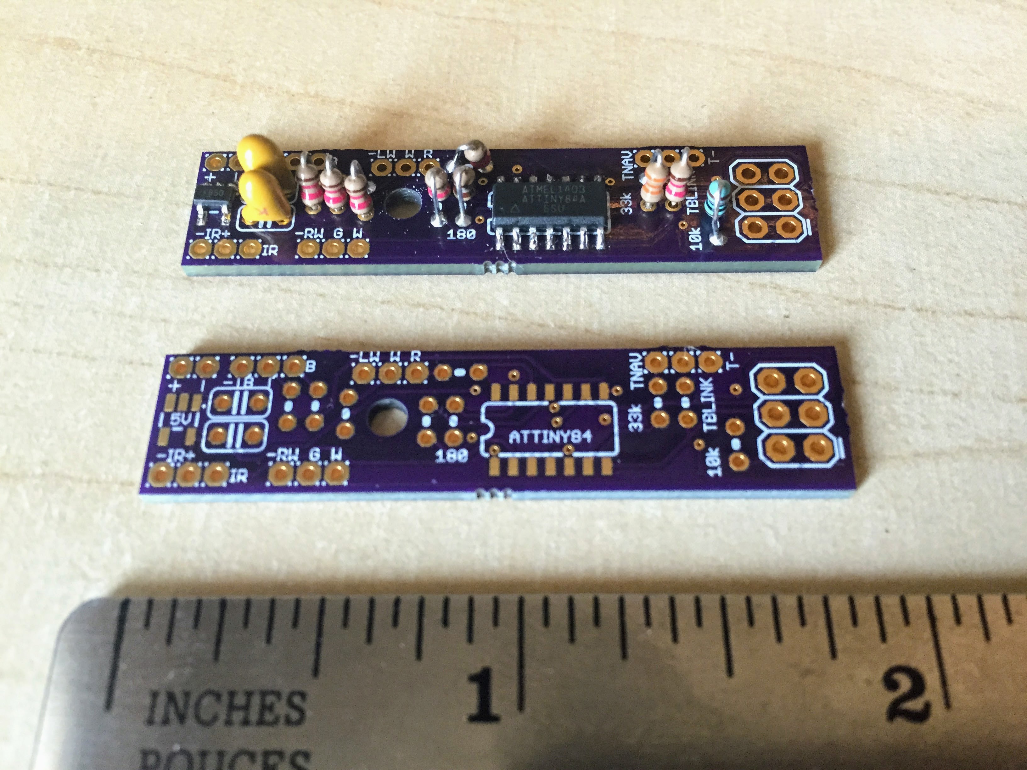 Having each component name, resistor value, and wiring pin printed on the board greatly sped up the assembly process and reduced errors. Using a PCB also meant that I didn't need to hand wire the back of the board as in previous versions.
I could have used suface mount resistors as well, but using verical mounting gives almost the same PCB footprint and is much easier to solder by hand.
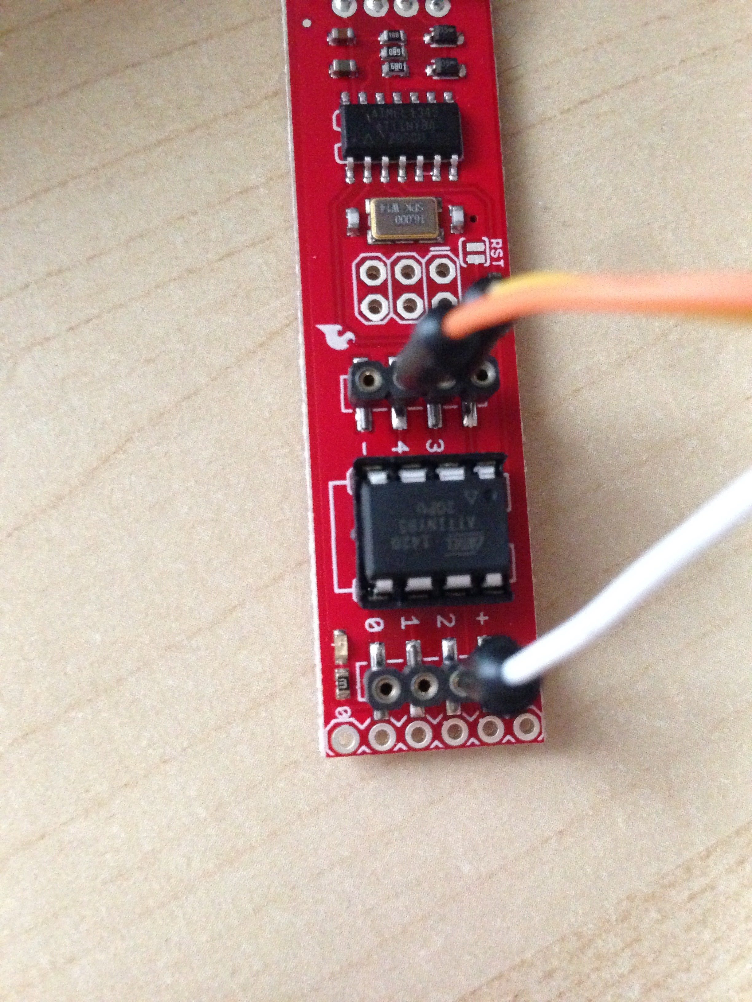
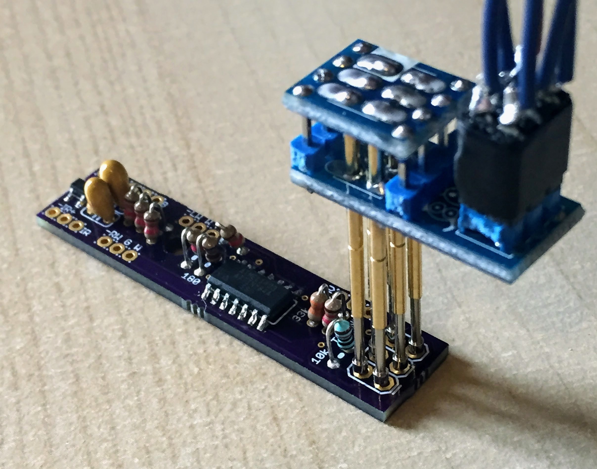 Loading code on the ATTiny84 is simple with an in-circuit serial programming (ICSP) interface via pads included on the circuit board. I use the same TinyISP programmer with a set of pogo-pins to
connect to the pads and write updated code just like flashing an Arduino over USB.
Model Kit
My original plan was to start with a typical hobby store model kit. Aircraft kits usually have a hollow fuselage and wings which would provide space for me to run wiring and store the electronics. Unfortunately, I wasn't really happy with the 1:144 scale kits as the A320 would be almost a foot long when assembled. I also wasn't able to find the right combination of airline livery and aircraft type that I wanted for my project. What I ended up using instead was pre-painted 1:200 scale kits from Hogan Wings.
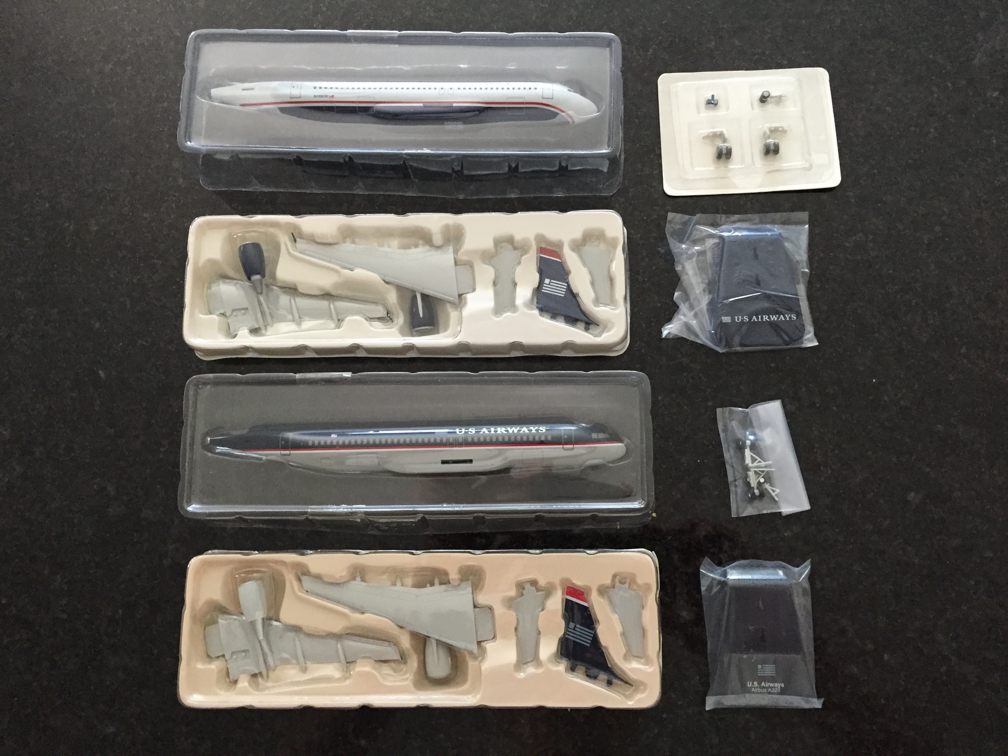 The kits come pretty much completed and are normally ready for display after snapping together just a few parts.
3D Insert & Stand
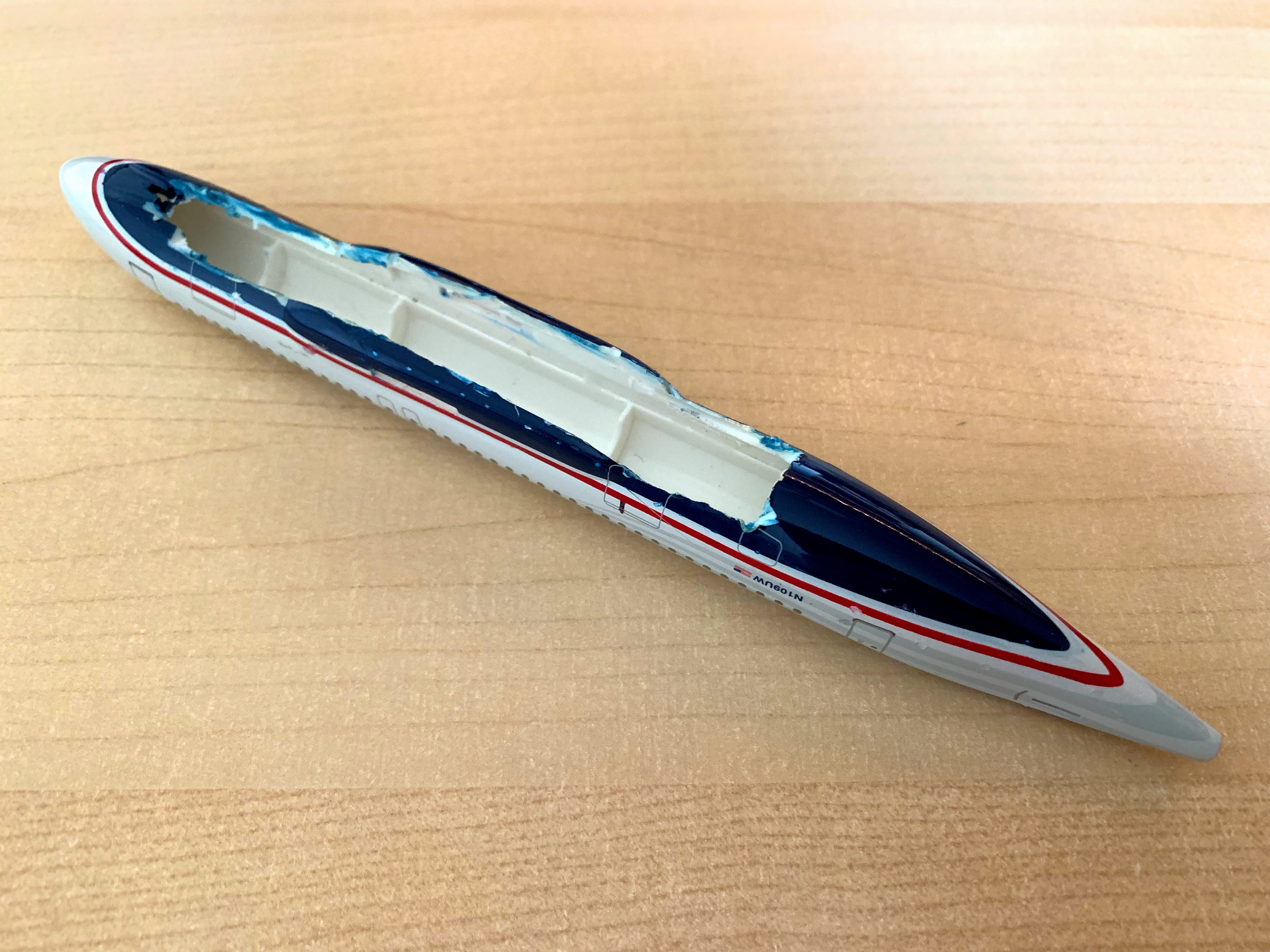
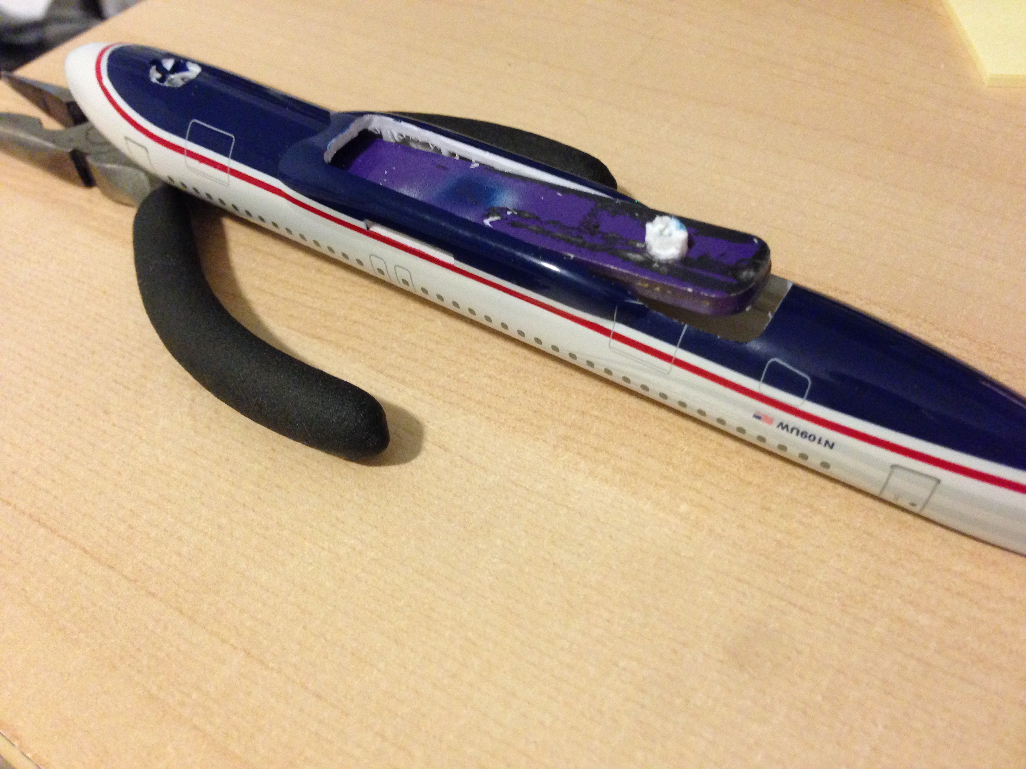
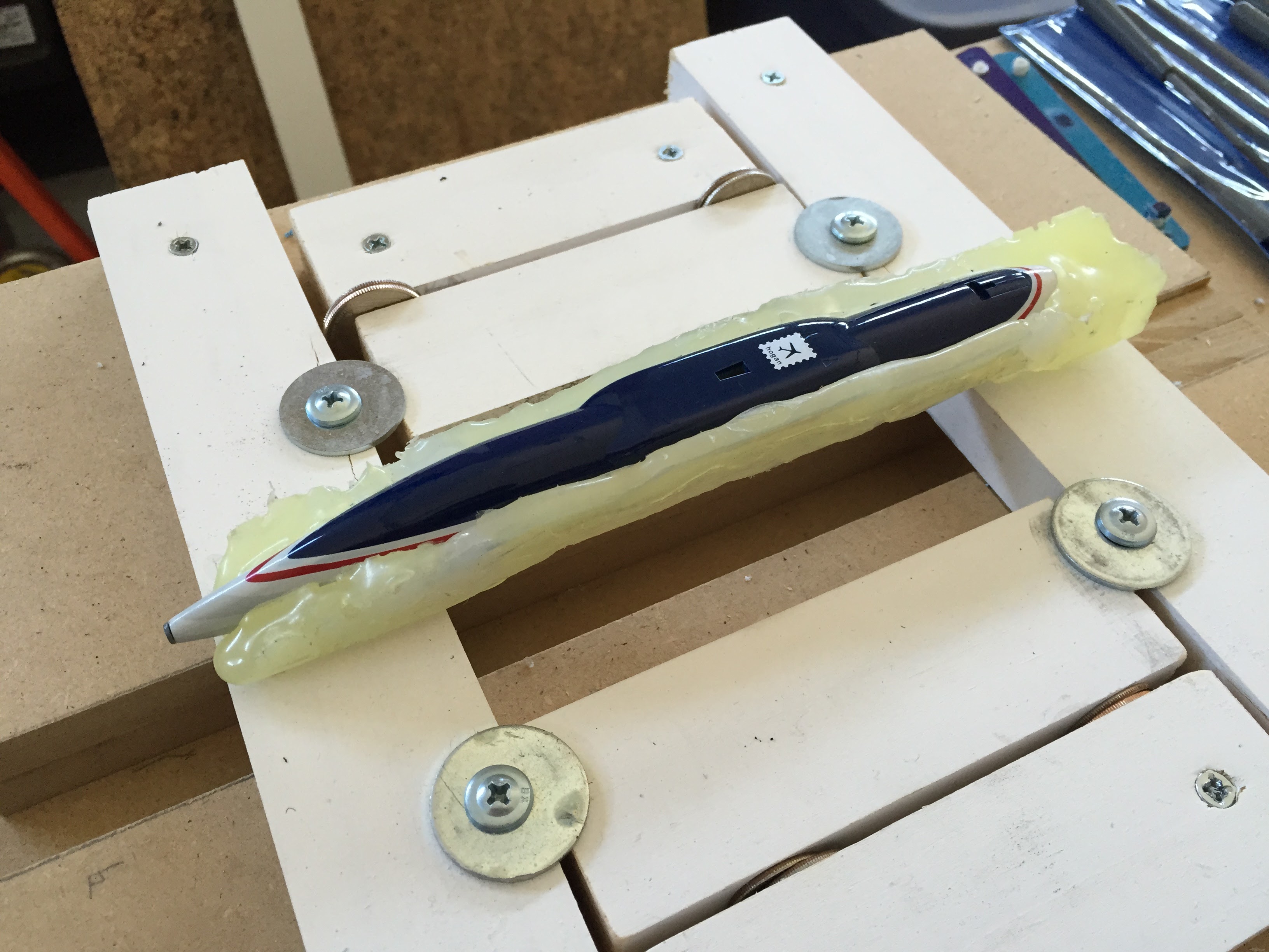
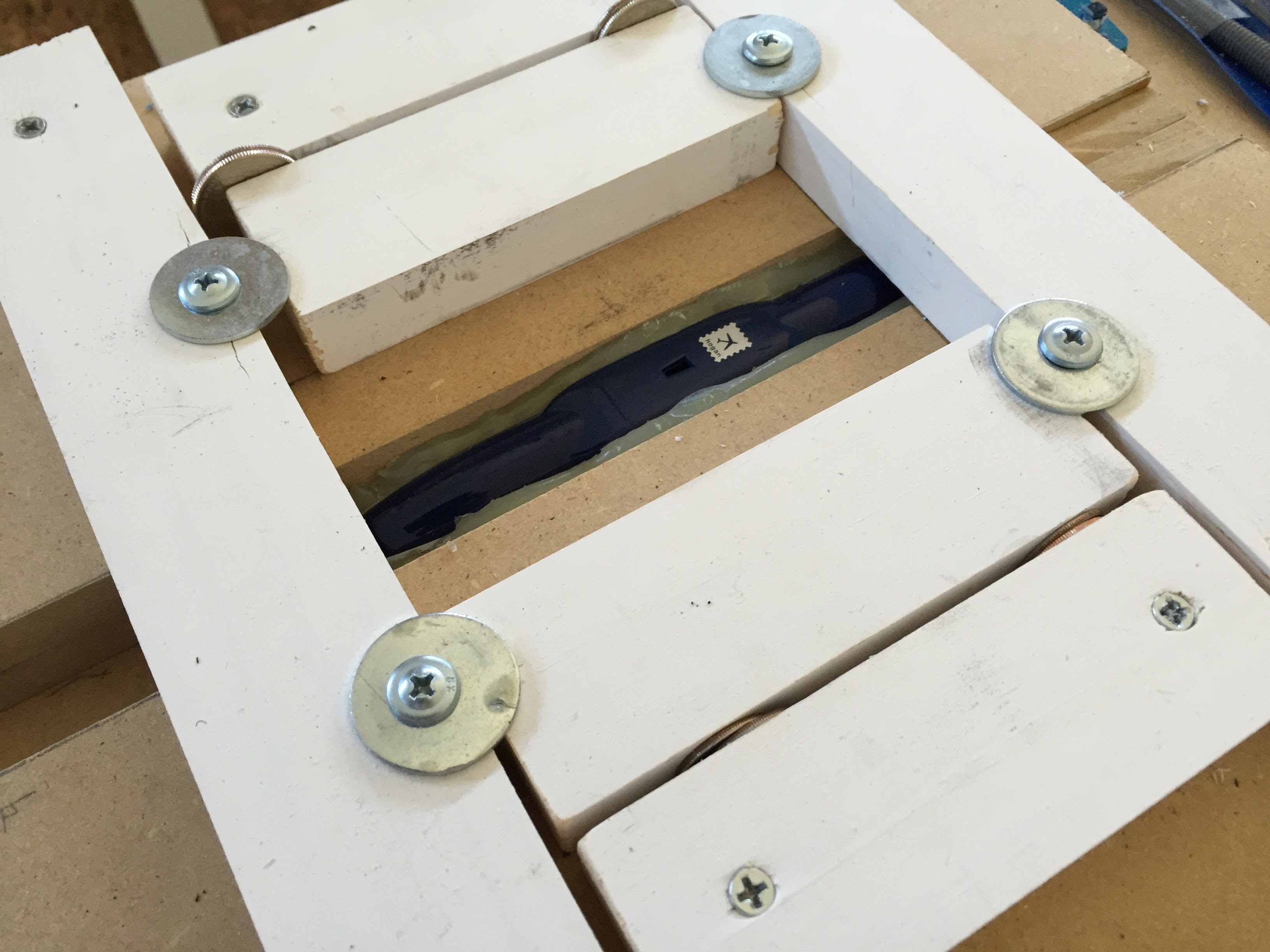
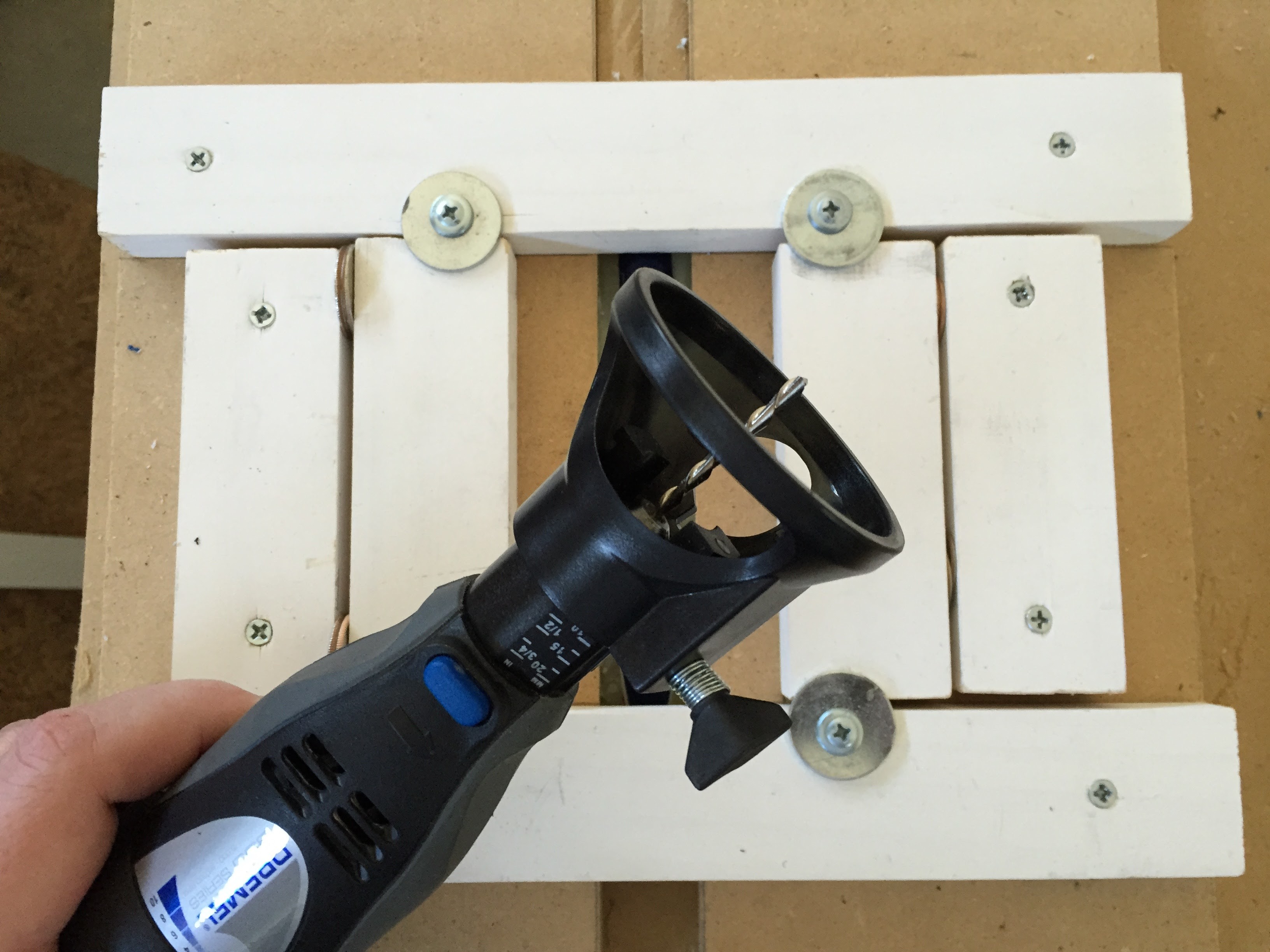
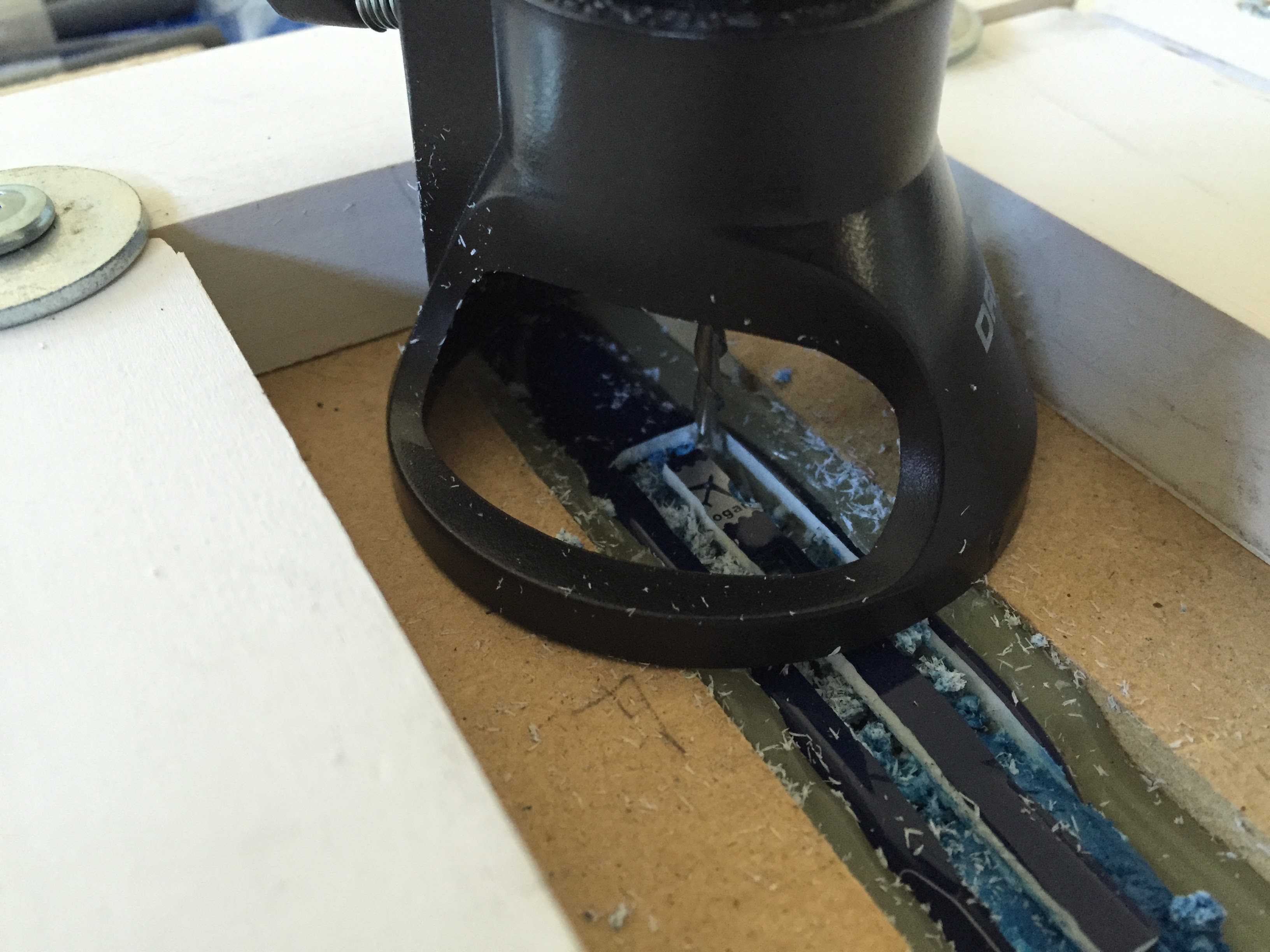
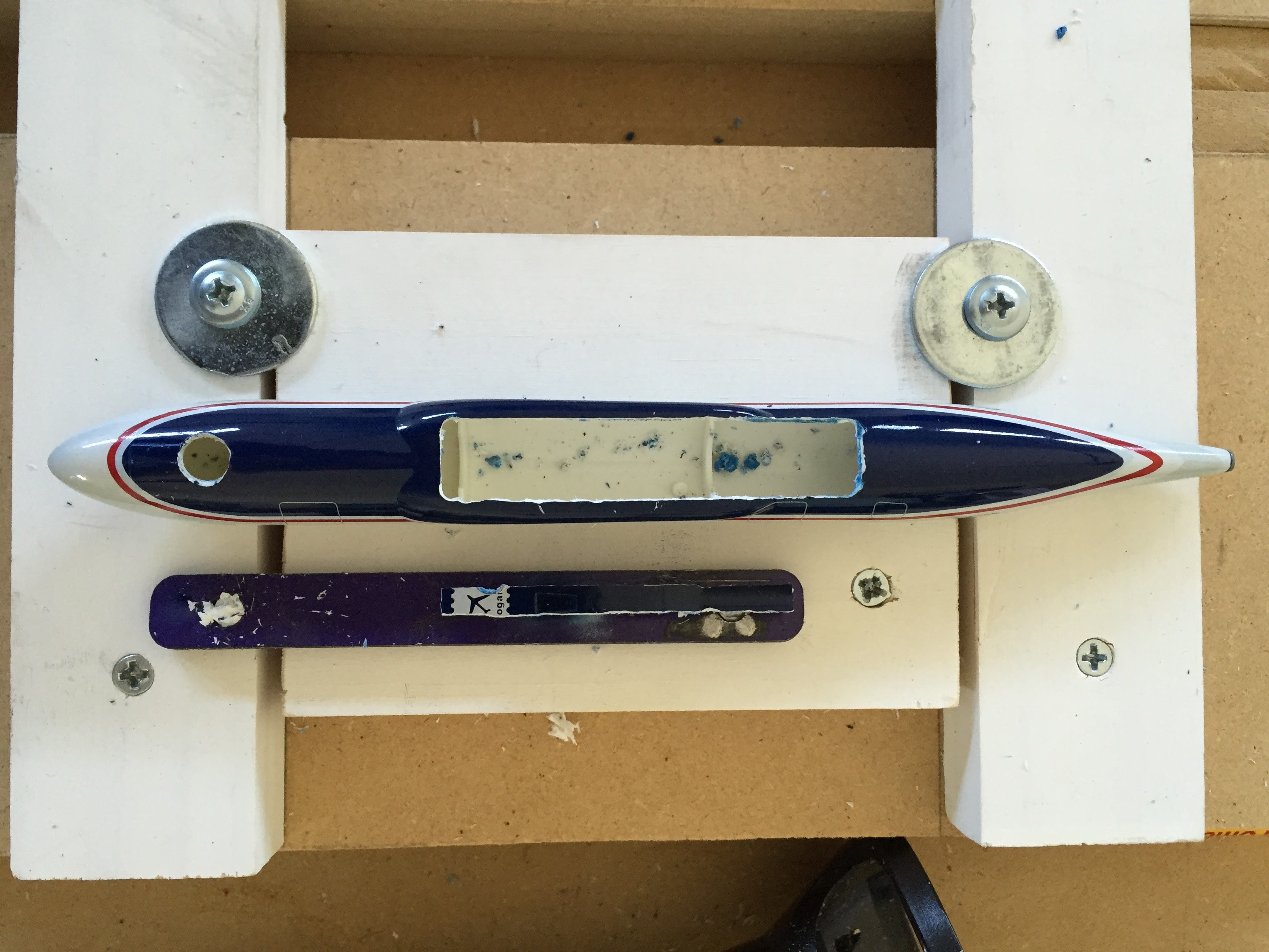
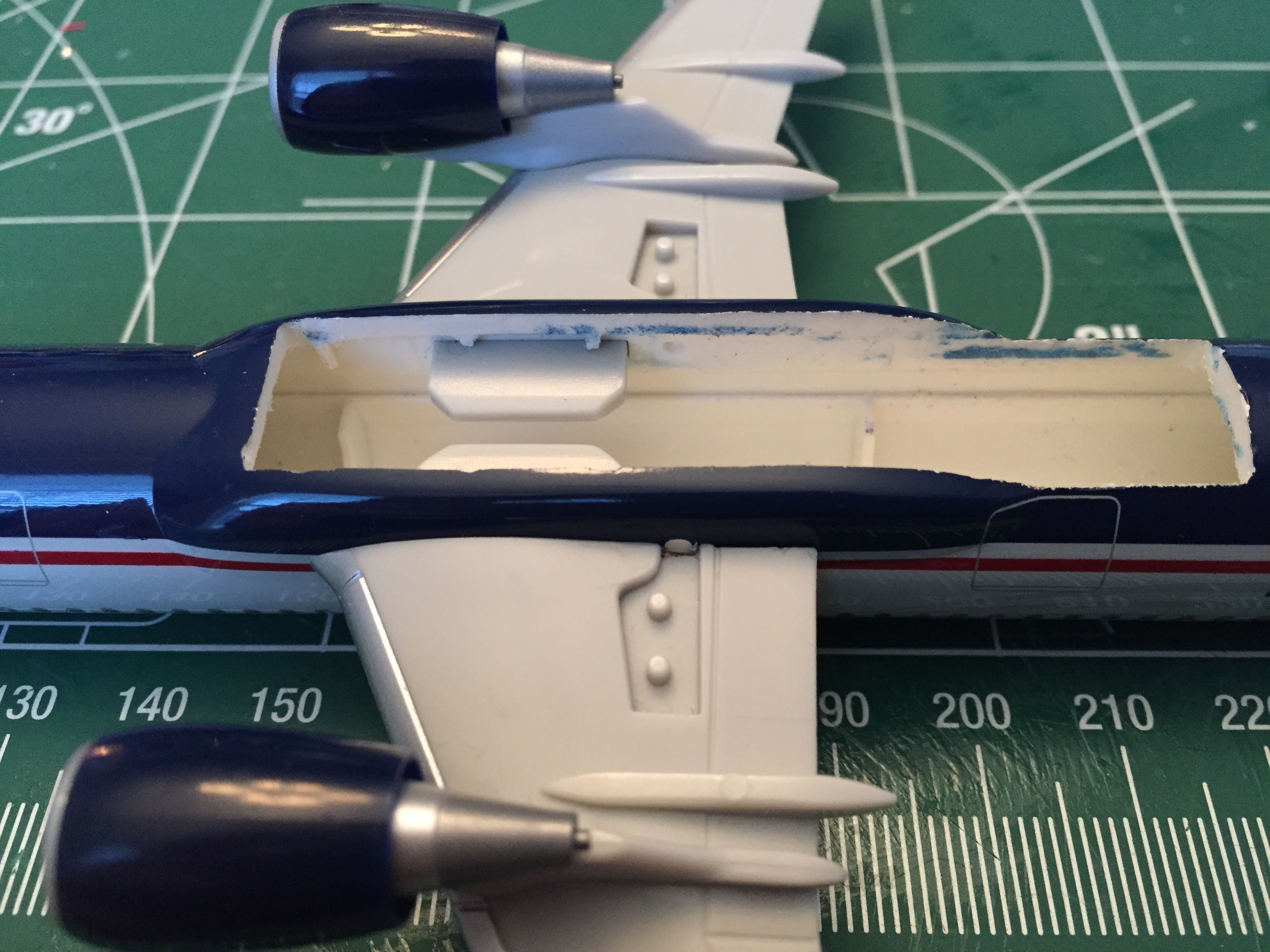
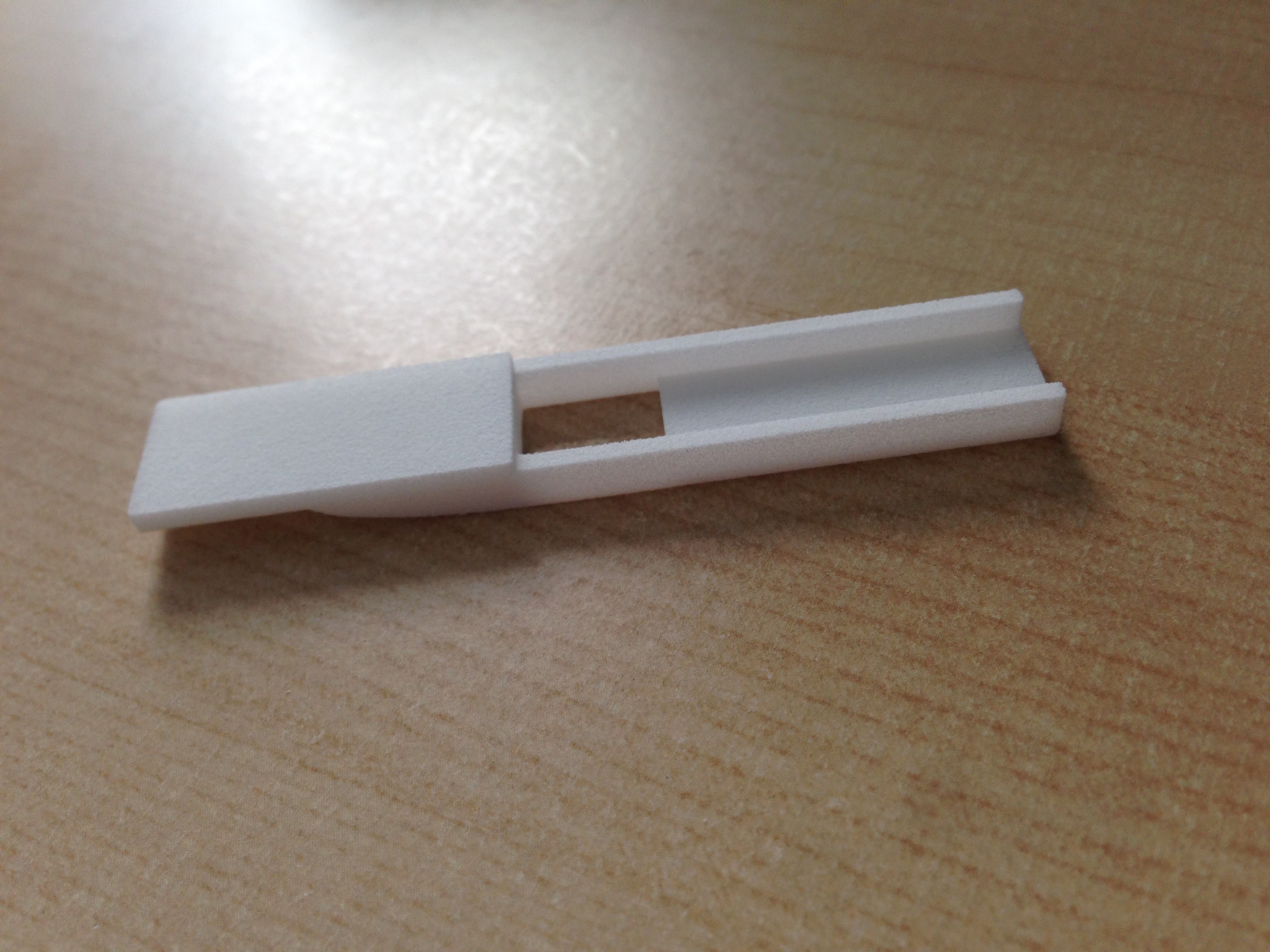
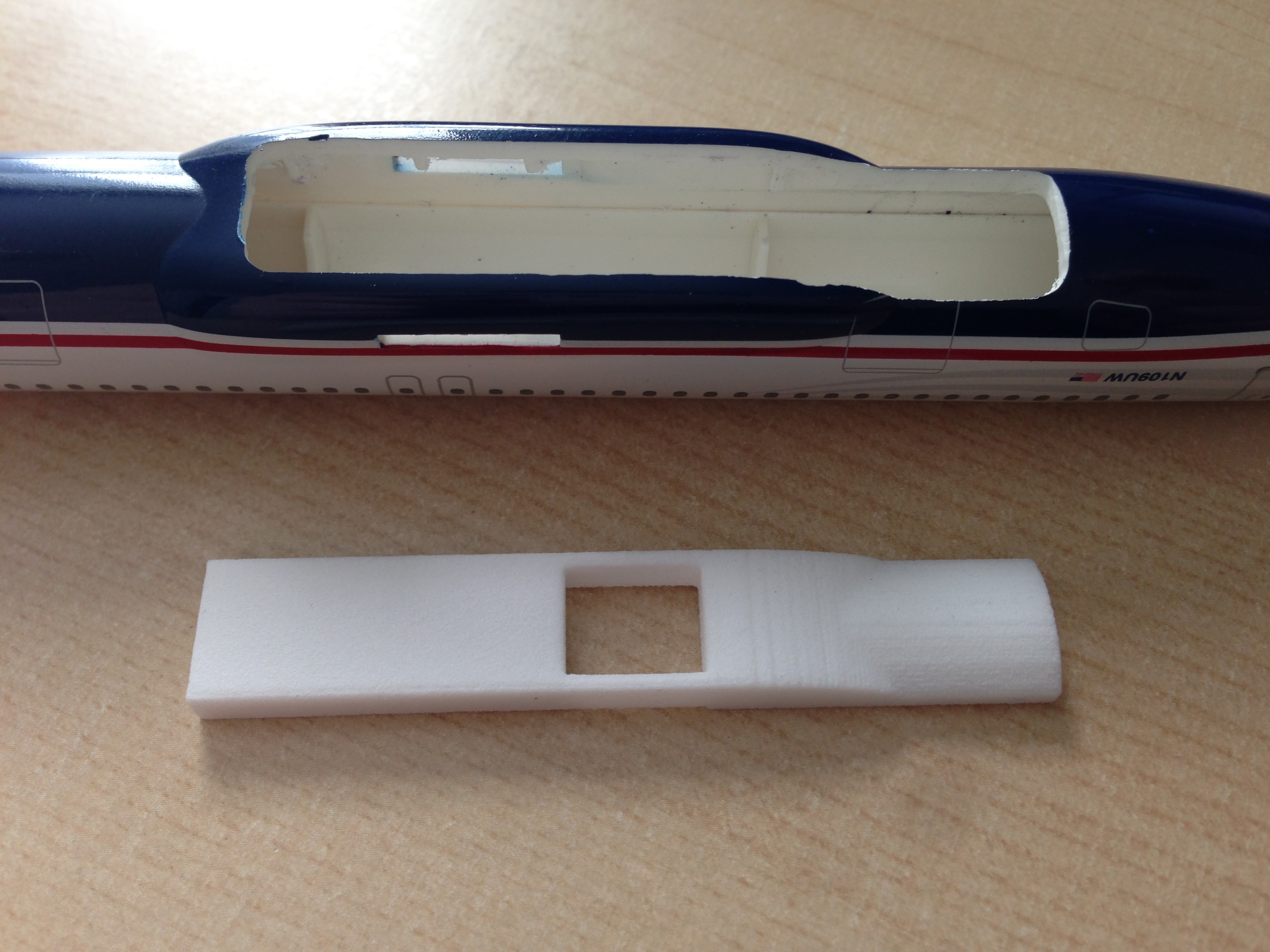
Once I had a repeatable way to cut the bottom of the plane out I knew that a 3D printed insert would be my best option for creating a replacement piece. I had originally considered resin molding as that would allow an exact replica of the outside of the aircraft but discarded that idea when I started looking at the requirements for the internal portion of the design. I had already done some tinkering using Shapeways SLS plastic parts and thought it would provide the right mix of detail and durability for this project.
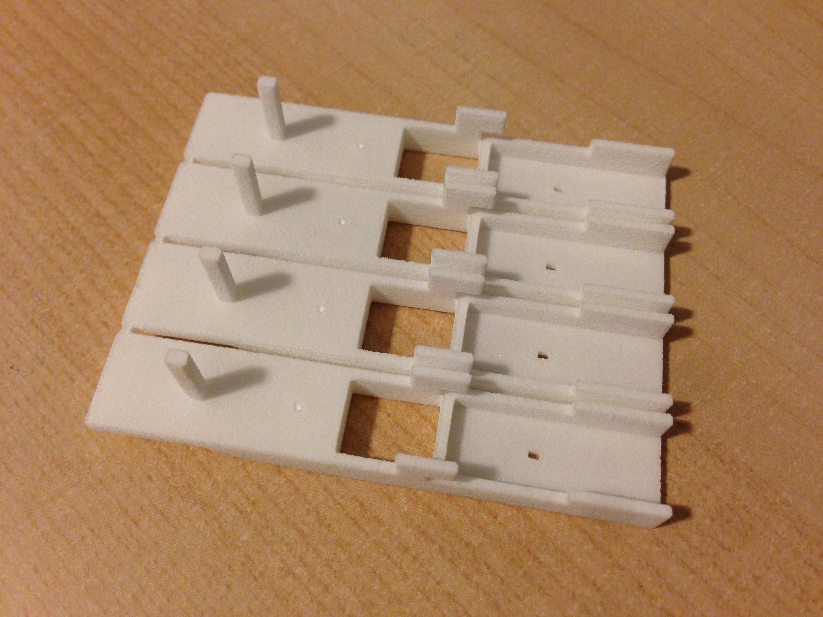
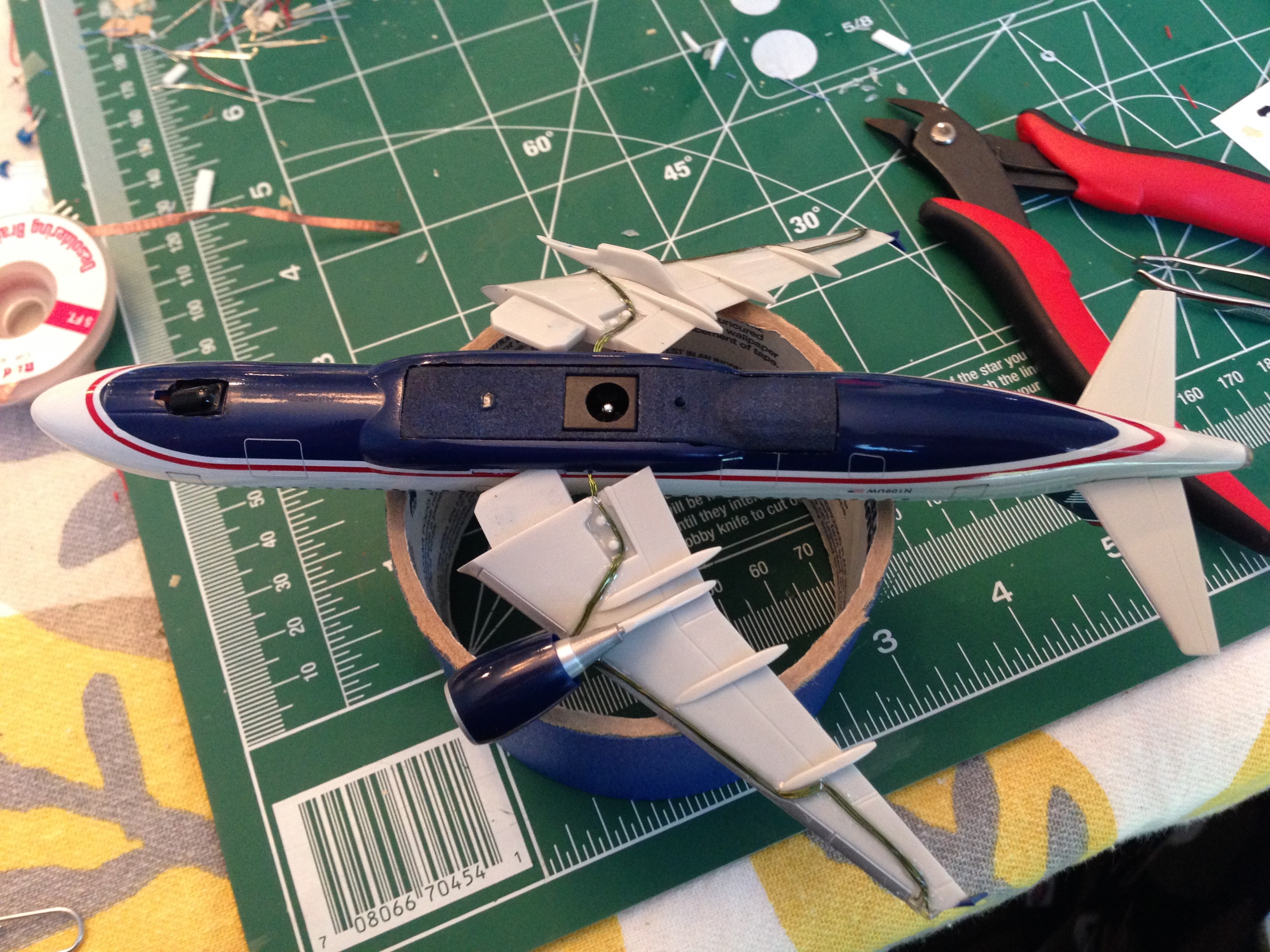
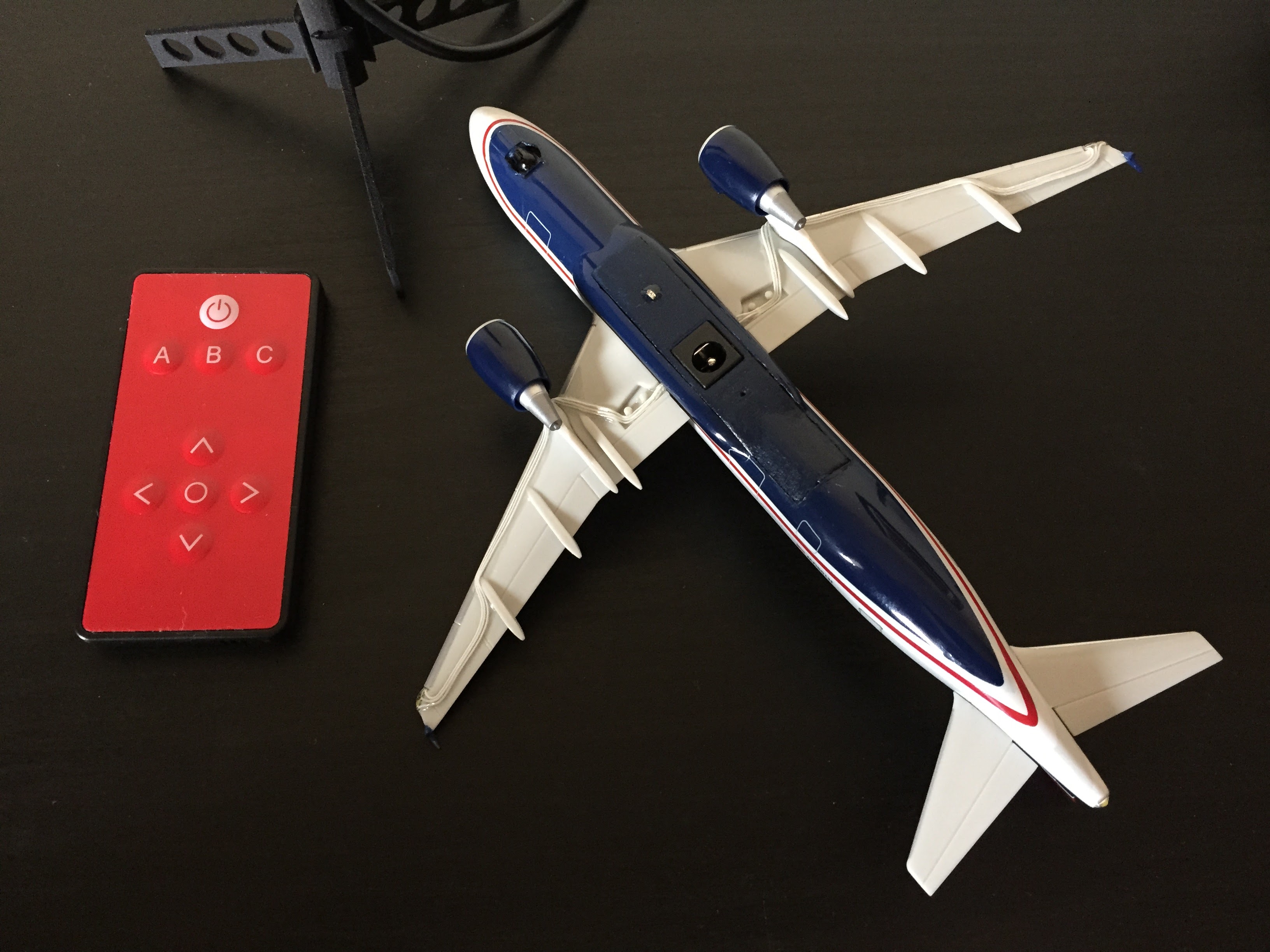
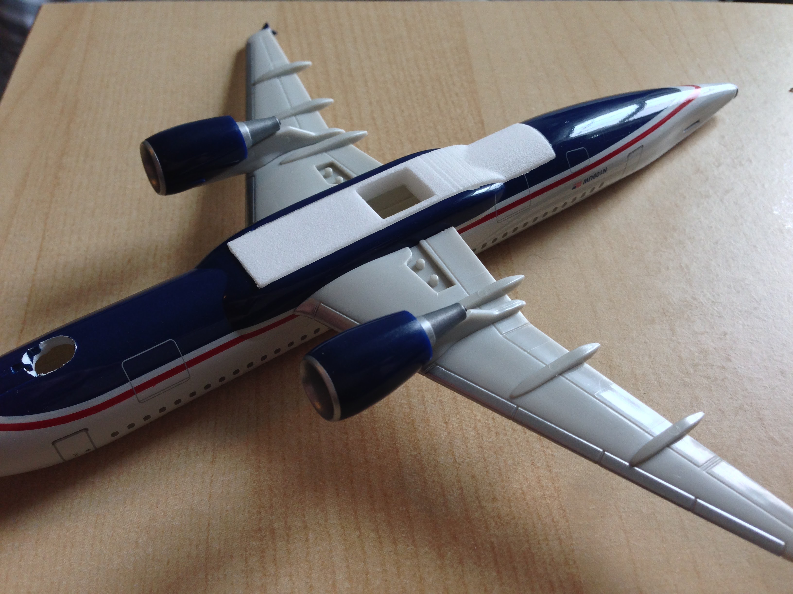 I designed this part to replace the missing section of fuselage. The center cutout was designed to hold a barrel jack which would also serve as the mounting point for the finished aircraft.
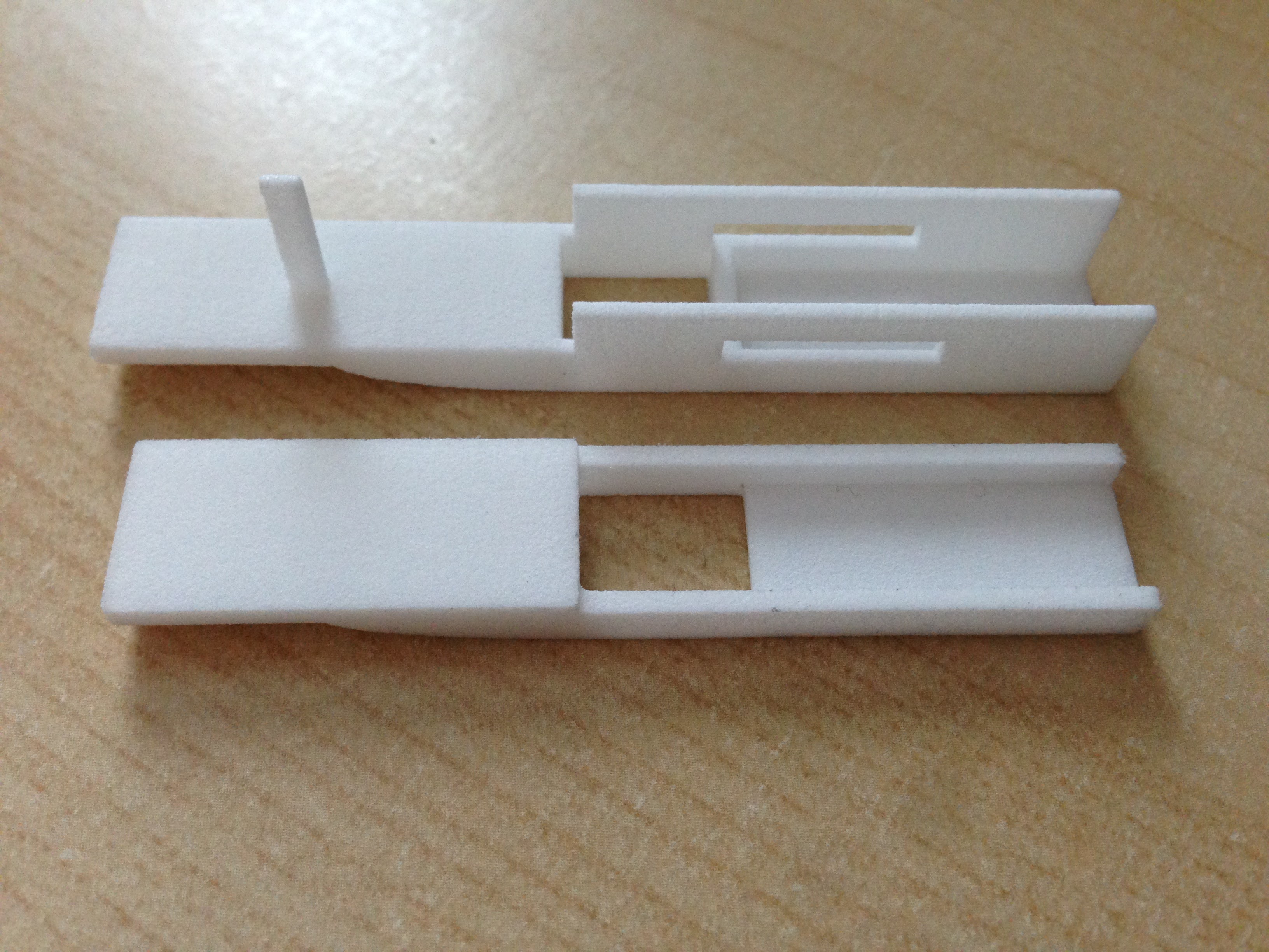
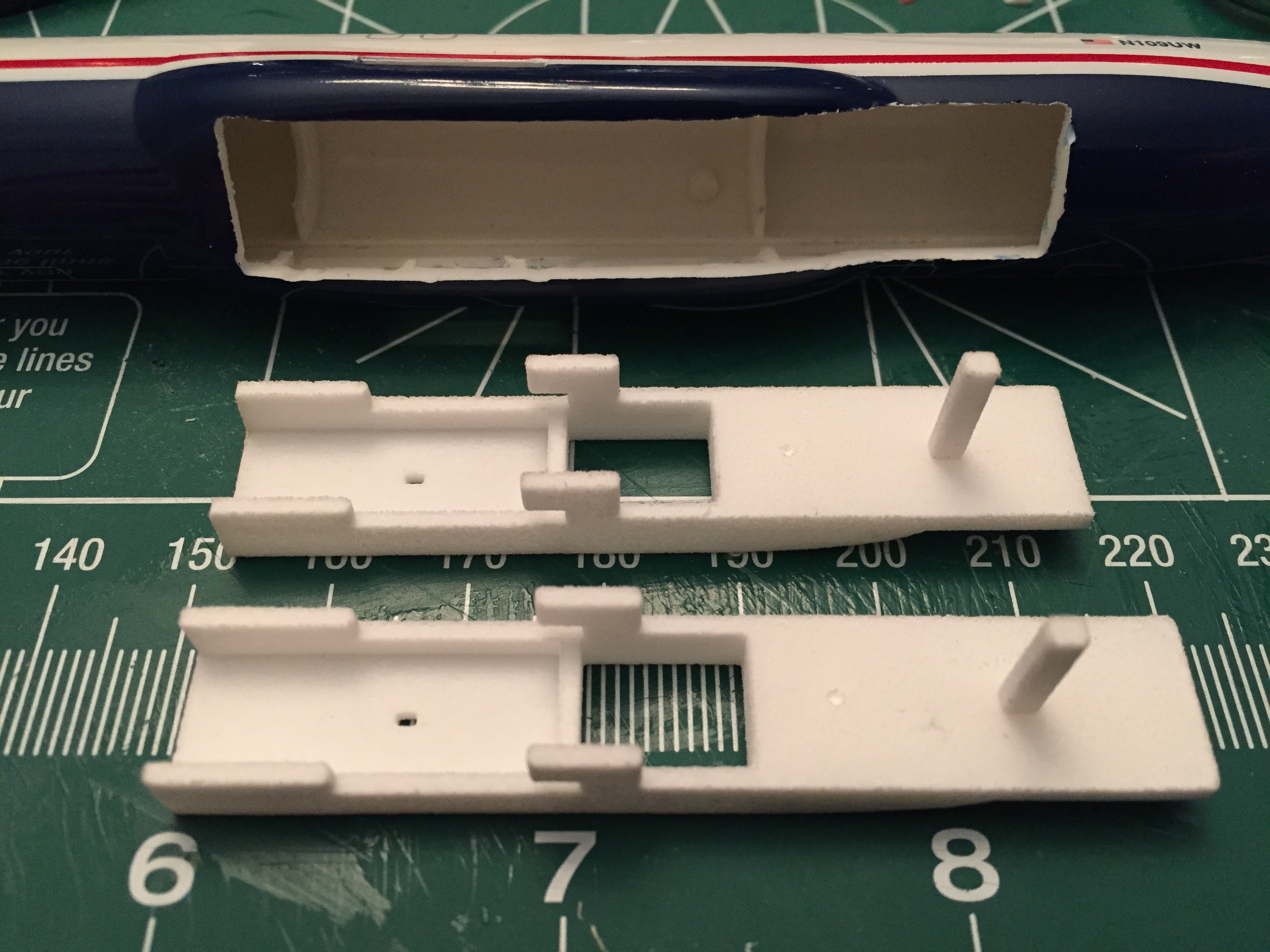 On the third revision of the insert I reduced the amount of material surrounding the wing tabs to just what was necessary to lock things in place. I enlarged the hole for the bottom LED as it had a tendency to get
filled in during the printing process on the previous revision. I also improved the match of the 3D-printed curves to the outside of the fuselage in a few places to reduce prep time before painting.
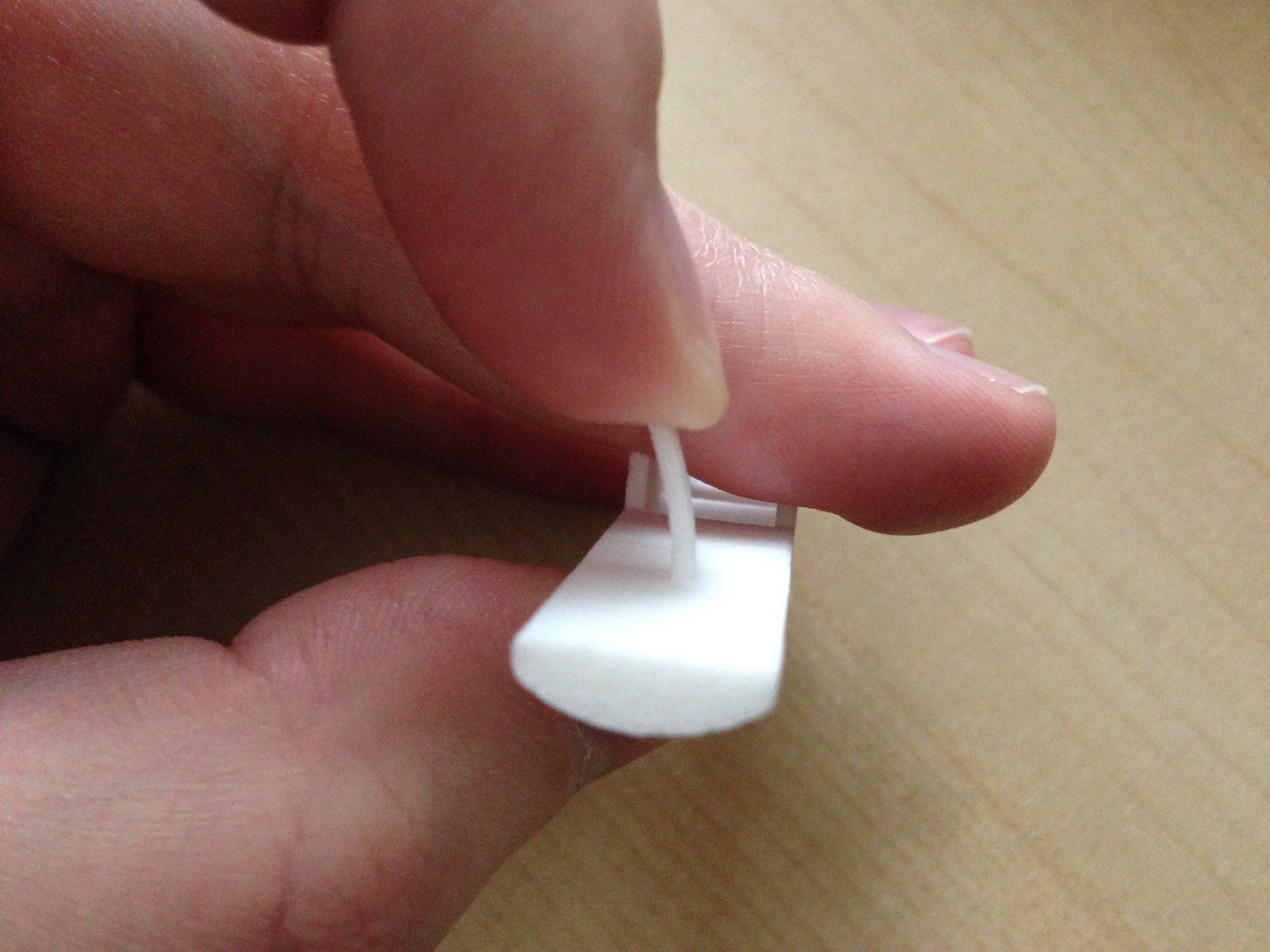
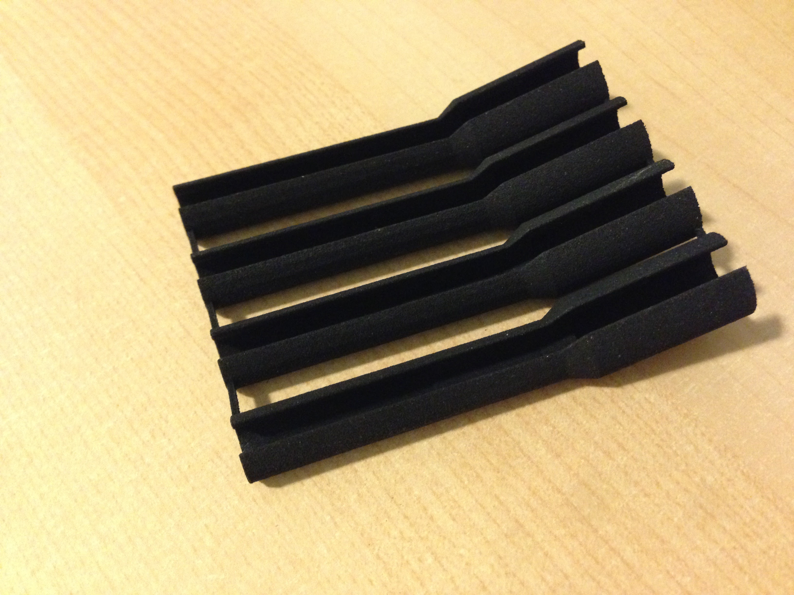
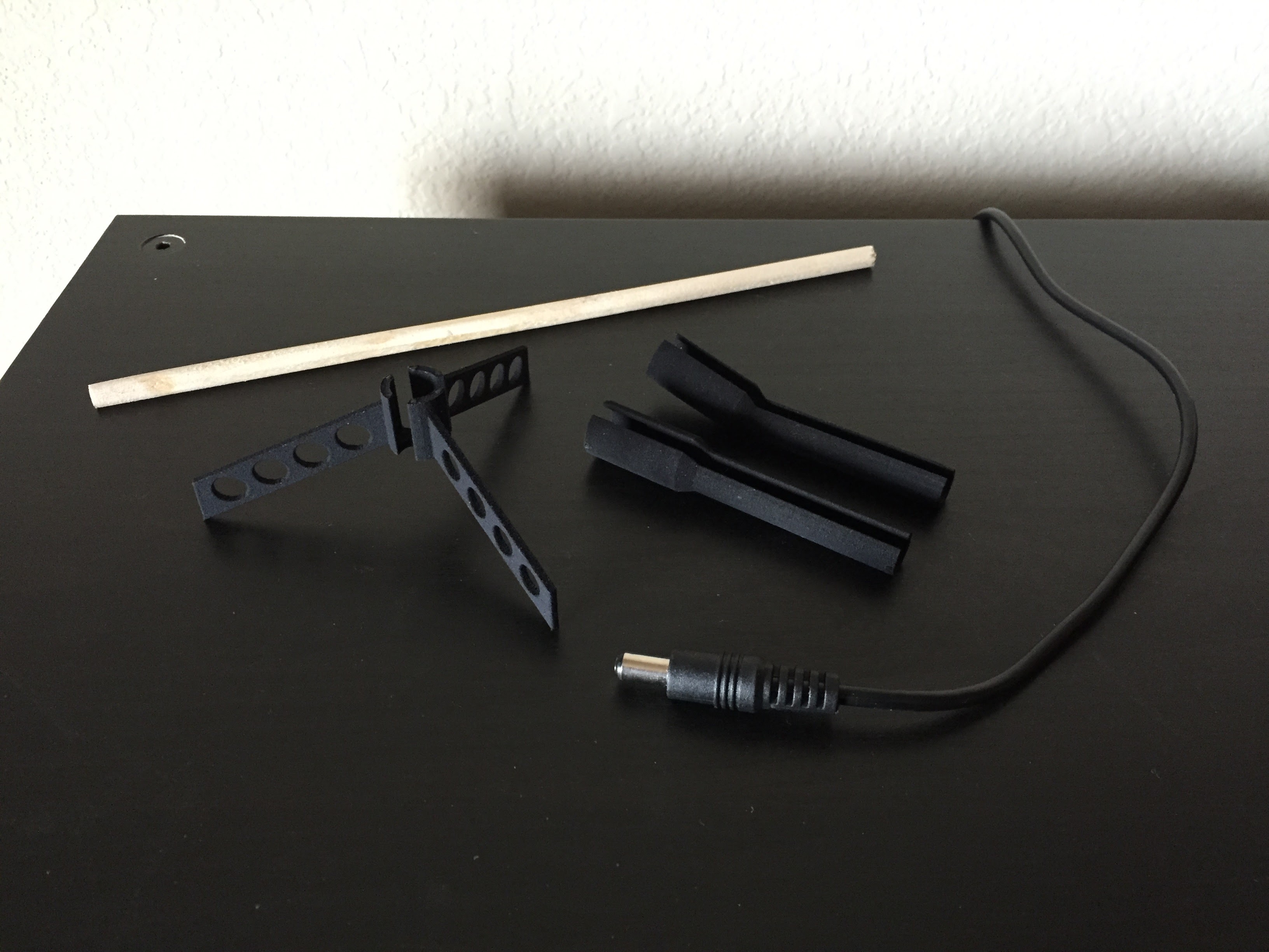
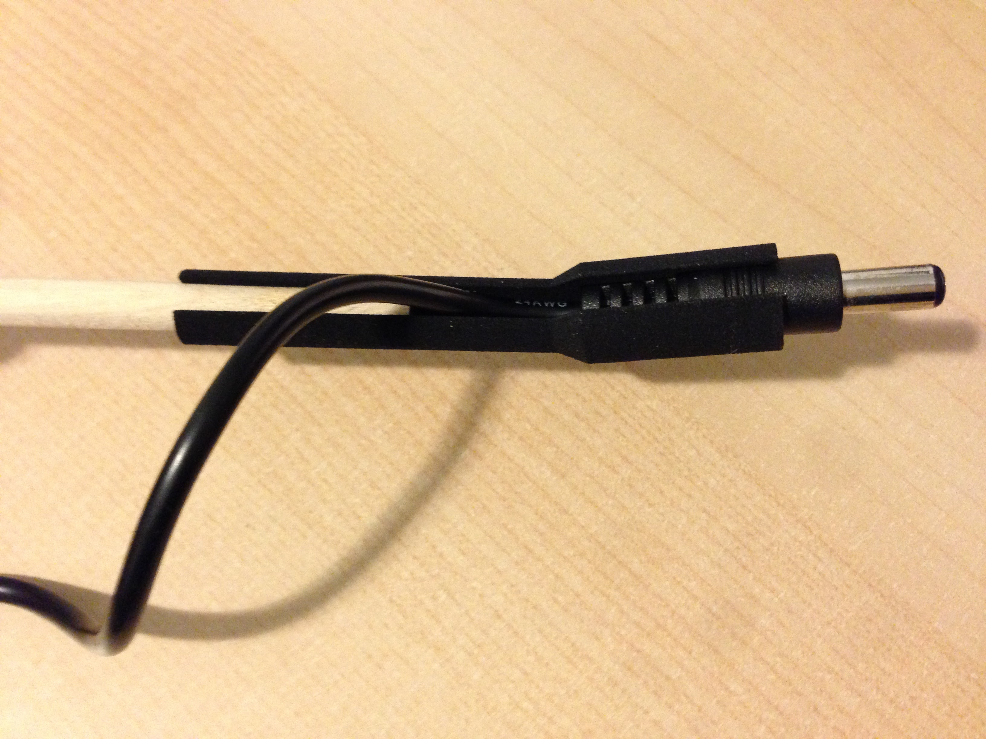 I needed a way to mount the plane and also a way to provide power so I combined them by using a standard 5.5 x 2.1mm barrel plug held in a custom 3D-printed mounting post. I added a 15° angle so that you could give the plane a more
dynamic in-flight look by rotating it on the barrel plug.
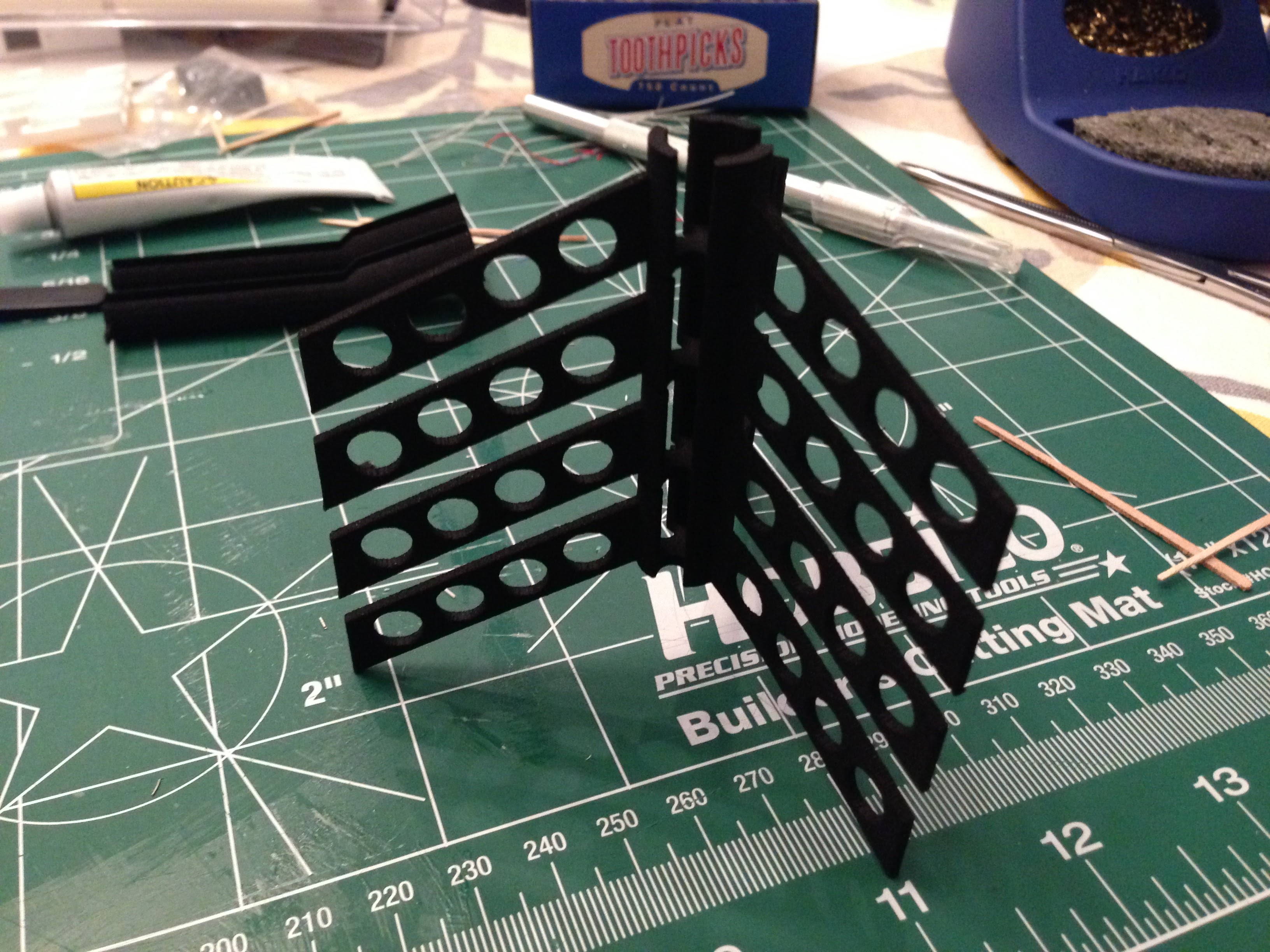
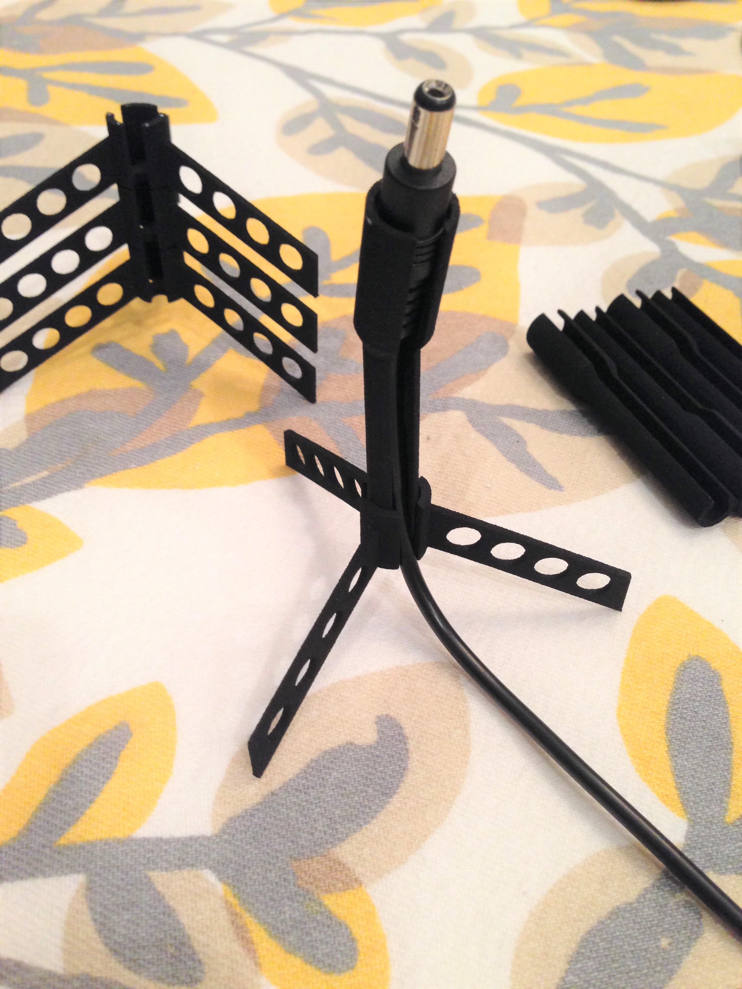 I also wanted a way to mount the plane for desk display so I designed a stand to match the mounting post.
Assembly
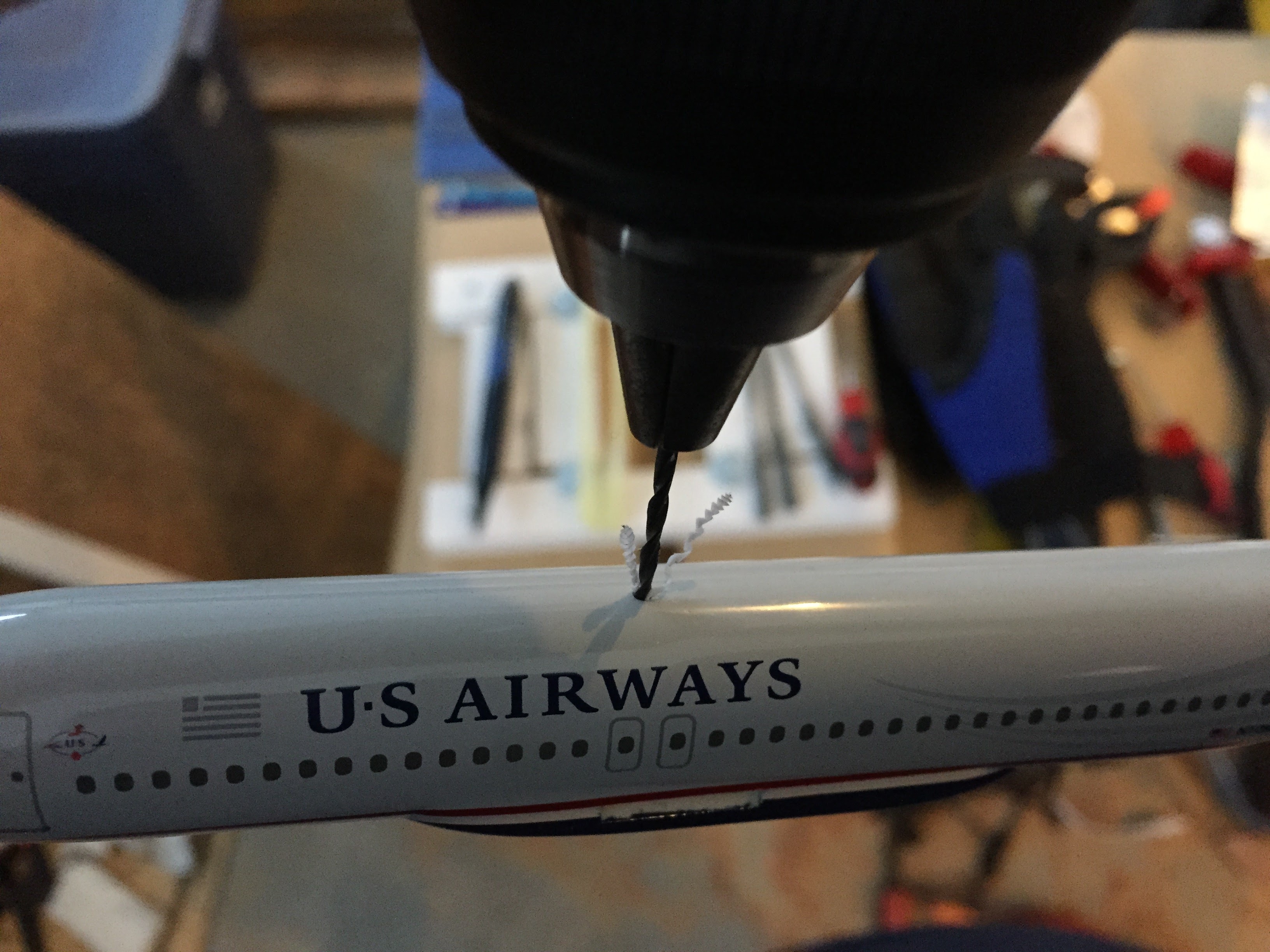
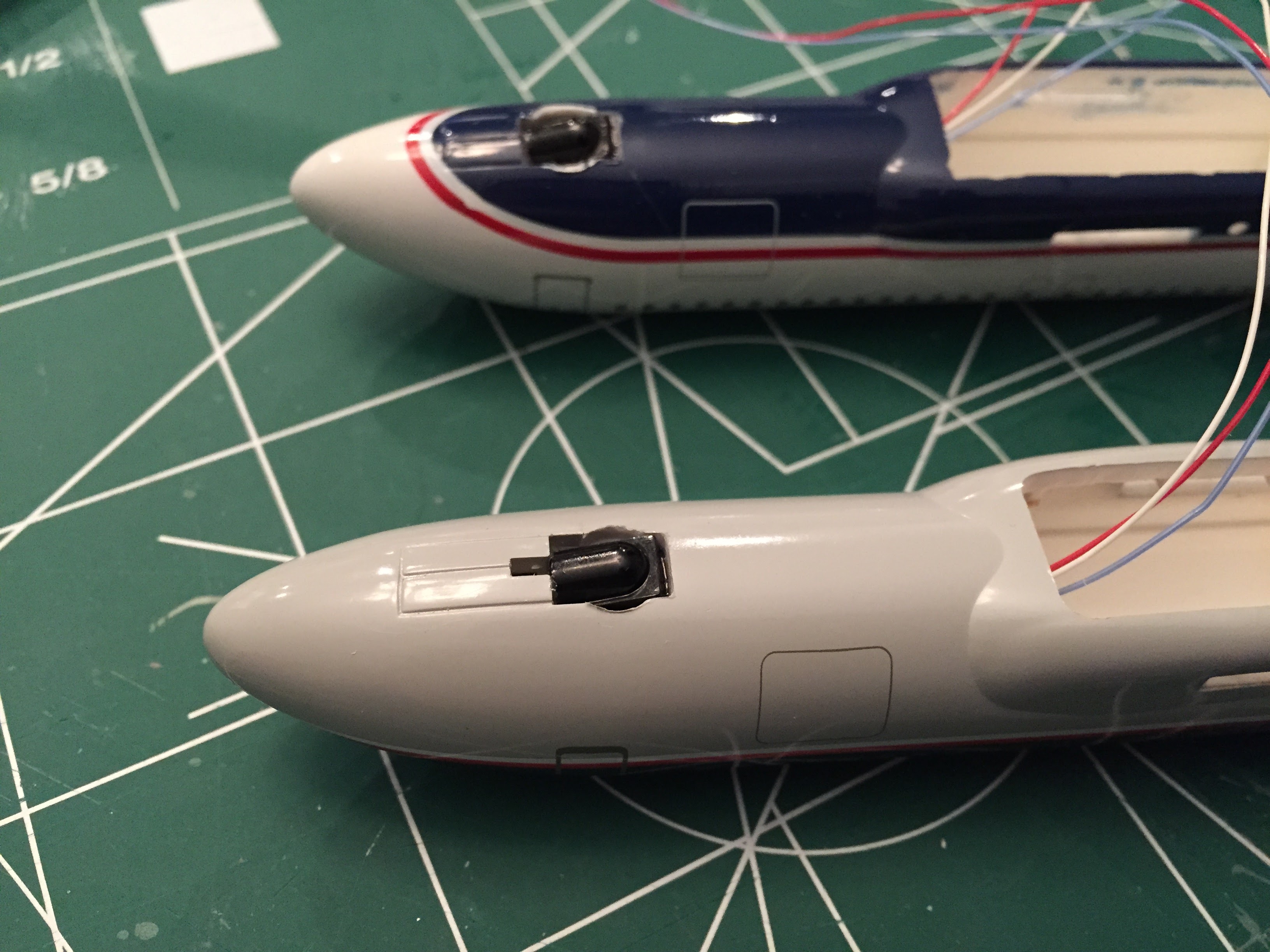 IR receiver modules are mounted in the nose of the aircraft. Due to drilling out the plastic mounting post for the zinc weight I already have a hole for the wiring. It's just dumb luck that the IR modules fit perfectly into
the molded wheel well on the kit.
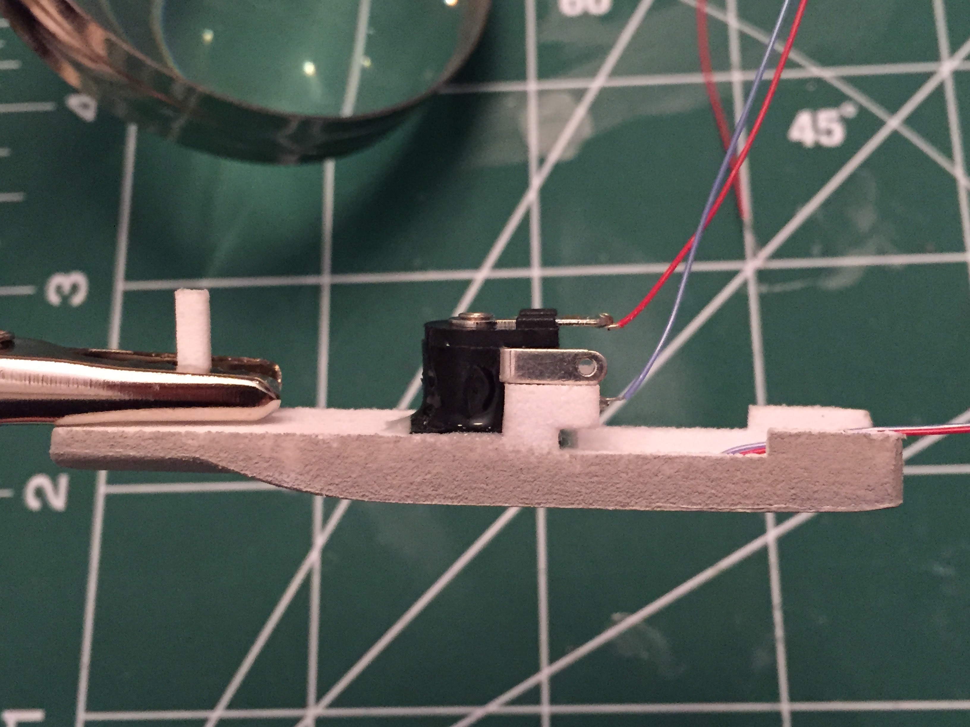 The barrel jack is mounted to the insert using epoxy. This part of the plane receives most of the physical force when inserting or removing the barrel plug so I designed the insert
to make sure there was enough surface area for a strong bond.
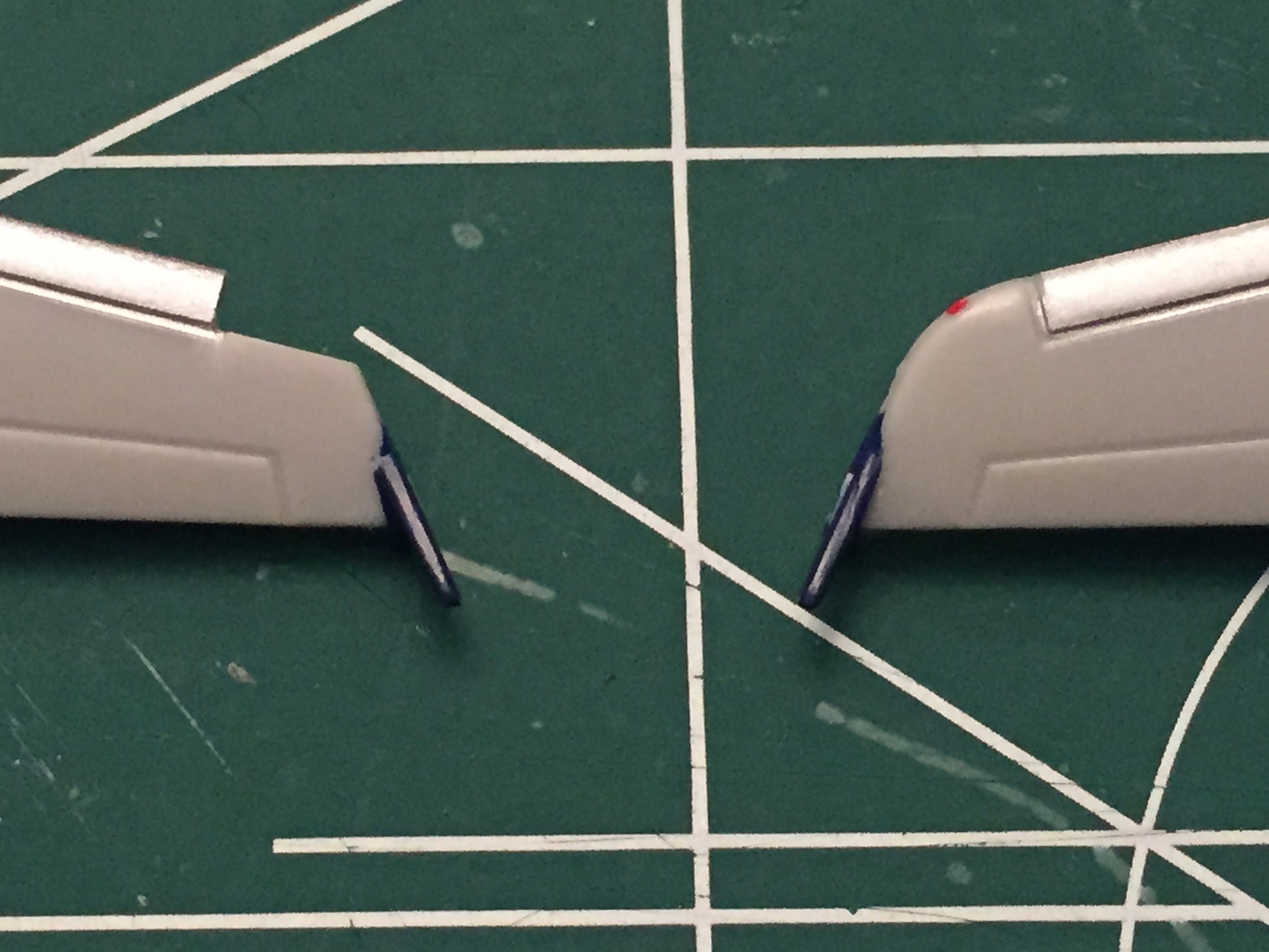
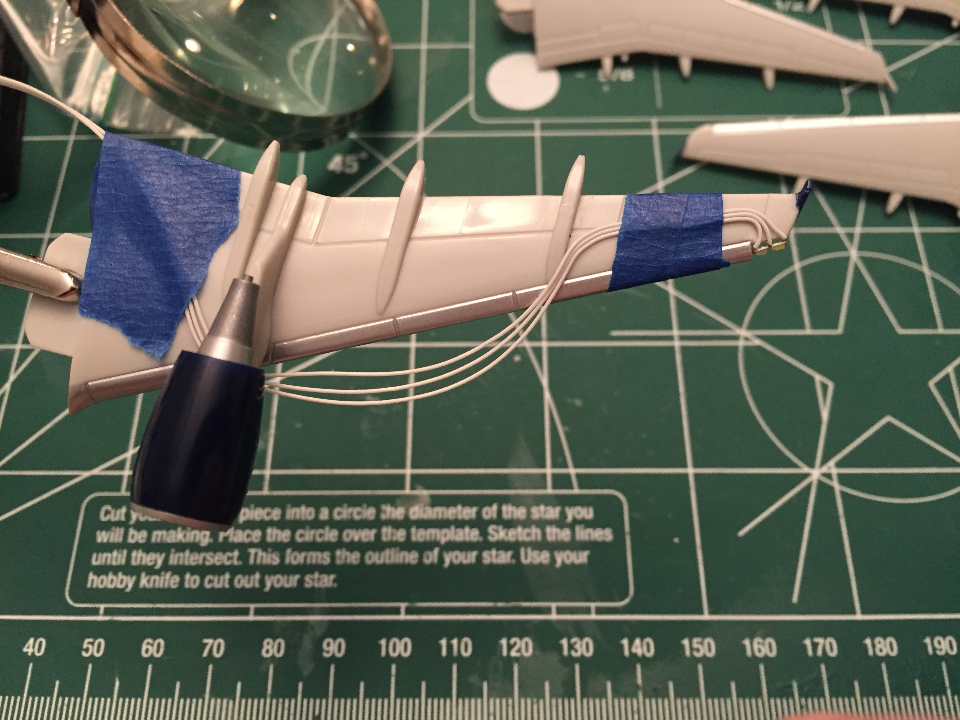
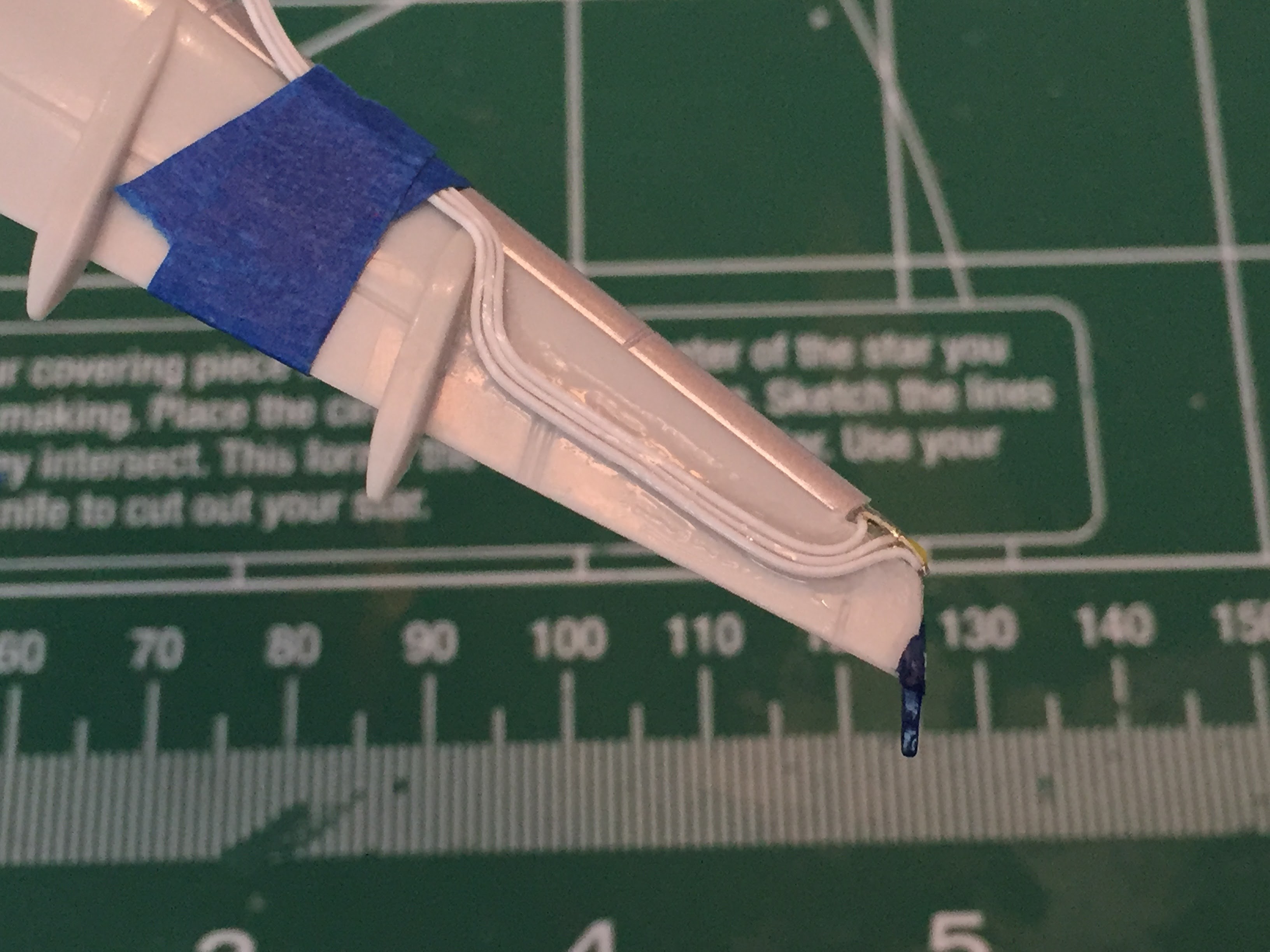
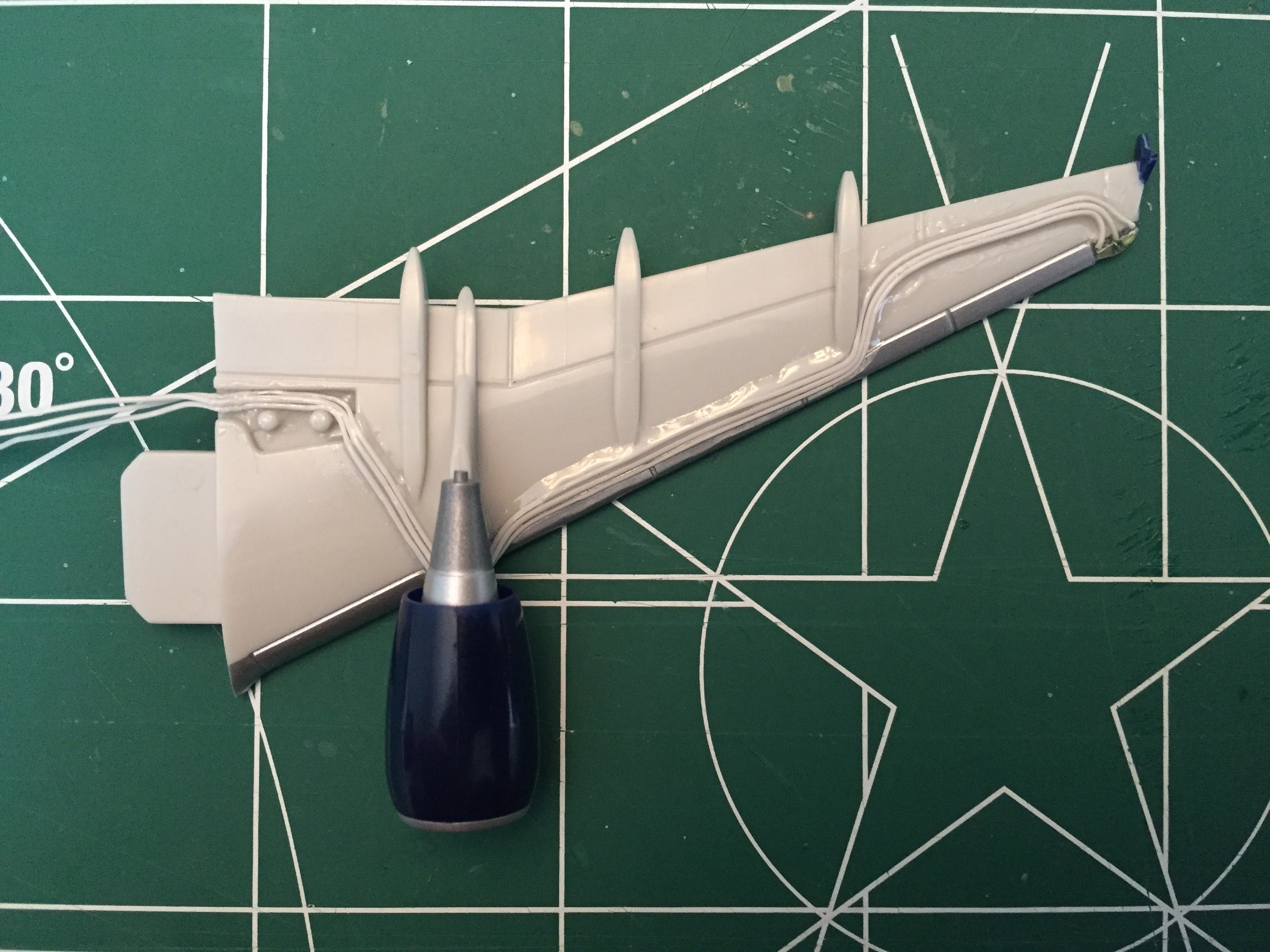 The wings are built by first cutting a notch in the wingtip to contain the LED assembly. Clear epoxy is used to secure the LEDs to the wingtip and also to build up a rounded protective layer that matches the shape of the original
wingtip area that was removed. More epoxy is used to secure the wiring along the underside of the wing. I don't like the exposed wiring but I switched to a light gray coated wire starting with my second build and it's much
less visible.
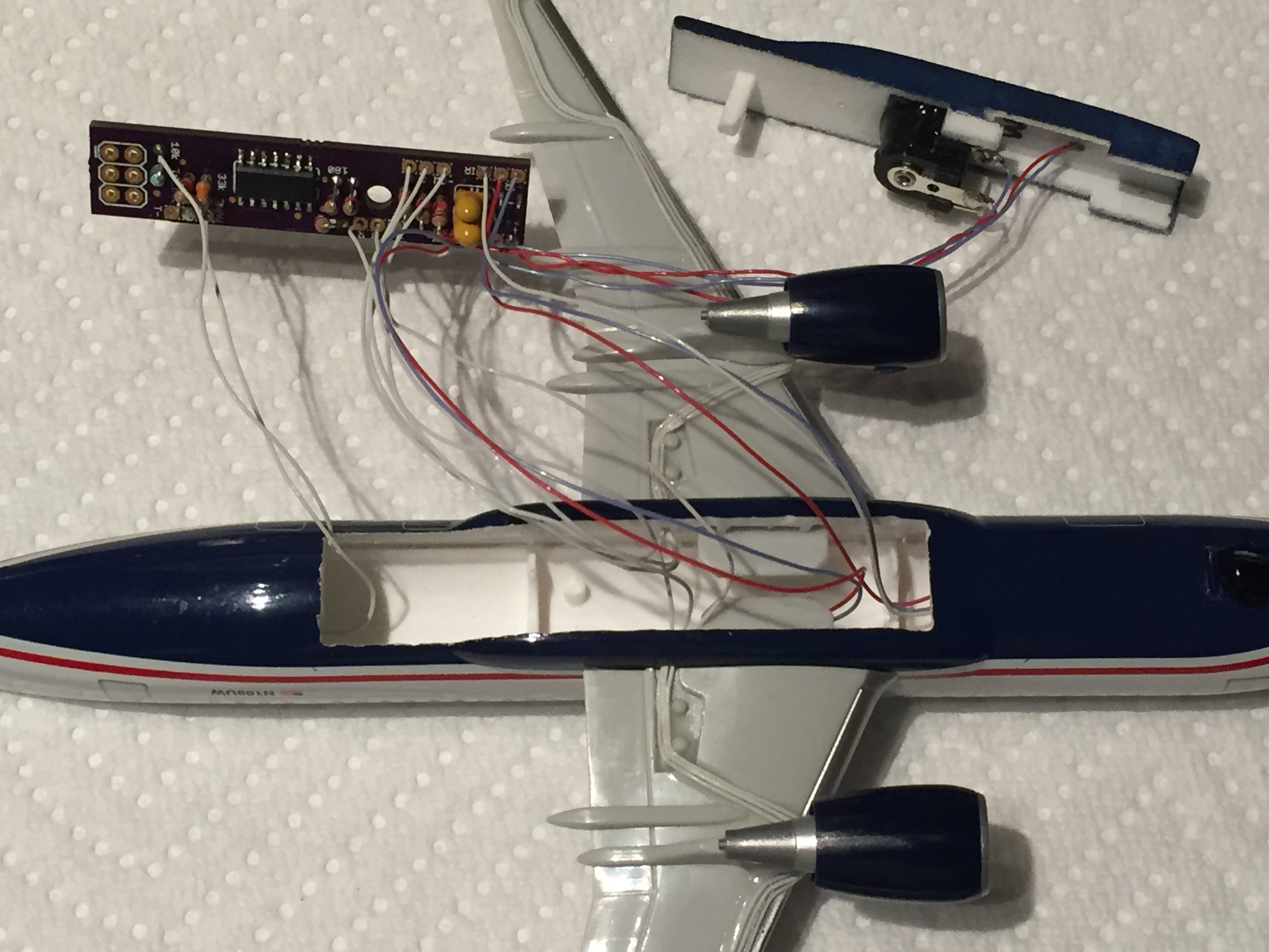
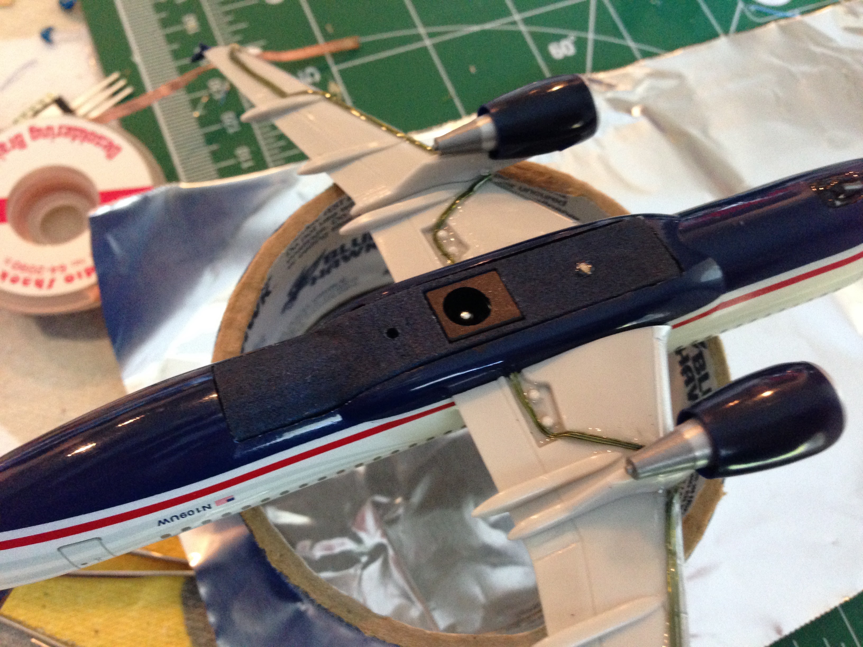 The wingtip LED connections must be run through wiring holes in the fuselage before being soldered to the board. Then the electronics are tucked inside the plane and the insert can be set into place. Finally, the wing tabs are inserted
into the slots which lock the insert into place and complete the assembly process.
